Rev. 2.0
Maintenance Guide
14-5
14-2. Power Supply Unit
14-2-1. Structure of Power Supply Unit (M and L Board Specifications)
The power supply unit is mounted on the front of the machine. Figure 14-2-1-2 show the structure
drawings of the power supply unit.
The power supply unit is composed of DC power supplies, control relays, and circuit protectors,
and designed to supply the AC and DC power to the units (control unit, X-Y unit, Z-θ unit,
transport unit, and head unit.)
The following shows the application of each DC power supply.
• +6V (+6.4V± 0.1V, PS1): For controlling of mechanical feeder (stacking, 32mm-paper tape)
• +24VA (+24±0.1V, PS2): General-purpose (For control unit outer board, stepping driver, etc.)
• +24VB (+24±0.1V, PS3): For control of Zθ-servo amplifier
• +12V (+12±0.1V, PS4): For S-VCS LED
14-2-1-1. Adjusting Method of DC Power Source Voltage Level
Table 14-2-1-1-1 DC Power Source Voltage Level Settings
No. Power
specifications
Power
symbol
Measurement terminals of power supply unit Voltage
adjustment value
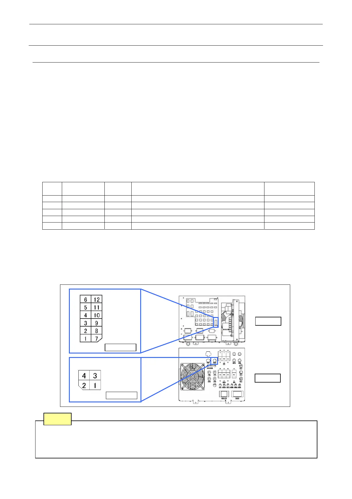
1 (∗) +48V - CN 039 Pin No. 1 (+48V) and Pin No. 7 (+48VRTN) -
2 +6V PS 1 CN 039 Pin No. 3 (+6V) and Pin No. 9 (+6VRTN) +6.4V±0.1V
3 +24V PS 2 CN 039 Pin No. 4 (+24VA) and Pin No. 10 (+24VARTN) +24V±0.1V
4 +24V PS 3 CN 039 Pin No. 5 (+24VB) and Pin No. 11 (+24VBRTN) +24V±0.1V
5 +12V PS 4 CN 060 Pin No. 1 (+12VC) and Pin No. 3 (+12VRTN) +12V±0.1V
• The DC power output voltage is to be adjusted on the CN039 and CN60 of the power supply
unit. (See Figure 14-2-1-1.)
• No. 1 with an asterisk (∗) are power supply lines not needing any adjustment.
• Pull out the power unit bracket, and adjust the output voltage variable change volume knob of
each DC power supply so that the output voltage values of the Nos. 2 to 7 DC power supply
are the specification values.
Figure 14-2-1-1-1
Note 1. Carefully adjust the variable resistor so that the voltage value does not become beyond the
specified adjustment level.
Note 2. Never use the GND line of a power supply unit other than that with the adjustment
instructed.
Do not connect such GND line.
Note
CN039
CN060
FRONT
REAR
Power
supply unit

 Loading...


