Rev. 2.0
Maintenance Guide
14-32
[Adjustment items after replacement]
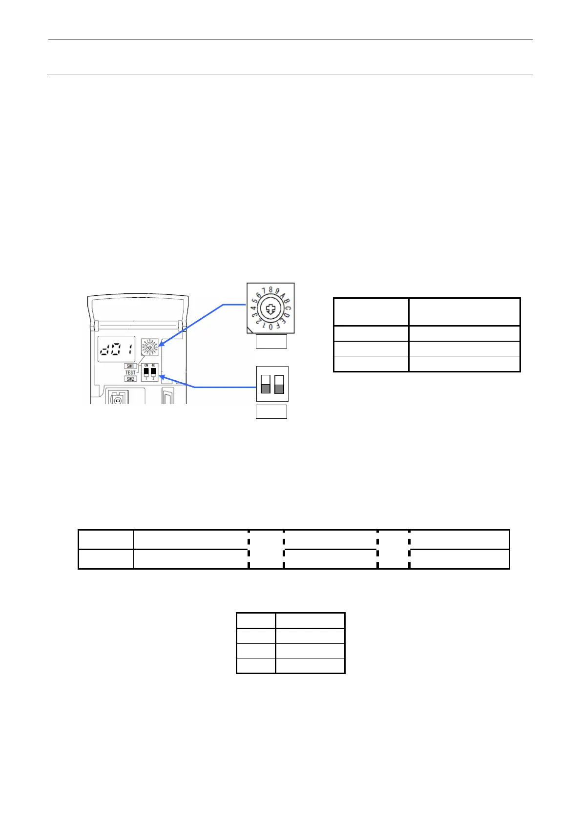
When replacing the servo amplifier, it is necessary to set the axis selection with the rotary
switch (SW1) on the servo amplifier of each axis.
Open the front cover of the servo amplifier and turn the rotary switch (SW1) for the axis
selection so that the arrow mark indicates the following set value.
Make sure that the DIP switch (SW2) is OFF.
After the adjustment has been completed, turn ON the power to the main unit and turn it OFF.
After that, restart the operation.
Note. When the main unit is started up for the first time after the servo amplifier has been
replaced, do not perform the origin return.
14-5-2. Display Indication of XY Servo Amplifier
A 7-segment LED that indicates the status is mounted on the front of the XY servo amplifier.
Normally, this LED shows the status as described below.
Table 14-5-1-2 7-Segment LED Indication
Indication Ab C# d#
Contents Initialization is in progress.
→
Servo OFF
→
Servo ON
∗ Axis No. is shown in the “#” portion. (See also the Table below.)
Table 14-5-1-3 7-Segment LED Indication
Axis Axis No.
X-axis 0
YL-axis
2
YR-axis
3
Table 14-5-1-1 Rotary Switch Settings
Servo amplifier
Axis selection switch
set values
X 0
YL 2
YR 3
1
2
ON
SW1
SW2

 Loading...


