Rev. 2.0
Maintenance Guide
14-35
14-7. Transport Unit
14-7-1. Structure of Transport Unit
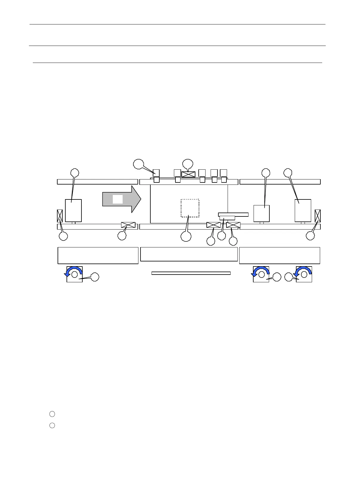
Table 14-7-1-1 shows the structure drawing of the transport unit.
Mount the BASE I/O board on the left of the front below the board base frame and the driver for
the transport stepping motor and the driver for the support table stepping motor on the right of the
rear on the base frame.
The support table is also called “BU (backup table)”.
It is not necessary to change the connection destination boards of the transport L motor, transport
R motor, transport L sensor, transport R sensor, and WAIT sensor inside the transport unit
according to the reference and flow direction.
1 Transport L motor (stepping motor)
d Transport CENTER motor (stepping motor)
e Transport R motor (stepping motor)
f Transport L sensor
g WAIT sensor
h STOP sensor
i C/OUT sensor
j Transport R sensor
k Stopper
l Y pusher
11
Support table motor (stepping motor)
12
BU origin sensor
Figure 14-7-1-1 Transport unit
A
1
1
3
32
2
4
5
6
9
7
8
10
12
11

 Loading...


