Rev. 2.0
Maintenance Guide
1-16
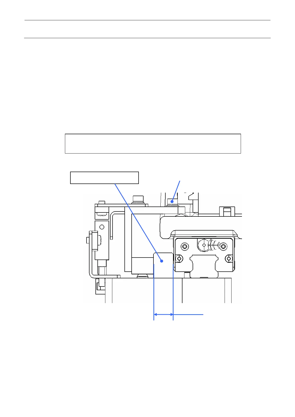
1-2-4. Clearance between the Sensor Head and Y-Axis LM Guide
(Y-axis_XL Board Specifications Only)
1) Put the 14mm-ceramic block and the MSC clearance jig (part No. 40098185) in the
clearance between the Y-axis LM guide and sensor head in the XY-axes full-stroke to check
that they are put in the clearance smoothly without play.
2) If the clearance is beyond 14.15 mm in the check conducted in step 1), loosen the screw
SL6041292TN fixing the sensor bracket.
3) Put the 14mm-ceramic block and the MSC clearance jig (part No. 40098185) in the
clearance between the Y-axis LM guide and sensor head, and then tighten the screw again.
4) Conduct the same check as described in step 1).
Clearance between the sensor head and Y-axis LM guide:
14.15±0.1 mm (Y-axis only)
14.15±0.1
SL6041292TN
Y-axis
Jig (Part No. 40098185)
Figure 1-2-4-1

 Loading...


