Rev. 2.0
Maintenance Guide
11-3
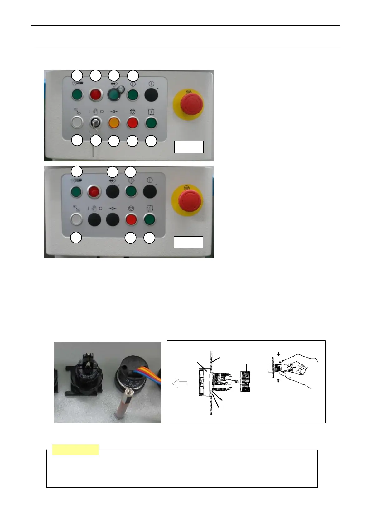
11-1-2. Replacing the Push-Button Switch (Machine with the EN Specifications)
c Feeder switch
(Provided when non-stop
operation is mounted.)
1 2 3
4
5
6
7 8
Front
9
d Laser ON lamp
(Provided when the optional
coplanarity is mounted.)
e On-line switch
f Start switch
g Keyboard setting switch
(Provided when rear
operation is mounted.)
h Key switch
i Origin switch
j Stop switch
k Single cycle switch
Rea
1
3 4
5
9 8
1) Detach the whole operation unit from the machine main unit. (M4 hexagon screws at 4
locations)
2) Detach the switch panel cover. (M3 hexagon screws at 4 locations)
3) Detach the operation board.
4) To detach the switch, remove the base part (mounting nut) of the switch from the rear of the
cover and pull out the case from the cover front. Then replace the switch.
5) Reassemble the components in the reverse order of disassembly.
Turn
Turn
Mounting
nut
Edge
Stop metal fitting
Groove
Panel
Pull out
Case
Back of Cover Detachment of Switch
A combination of the switch connector and connector on the operation switch board has
a specified orientation. Always pay special attention to the orientation when mounting
the switch.
CAUTION

 Loading...


