Rev. 2.0
Maintenance Guide
5-11
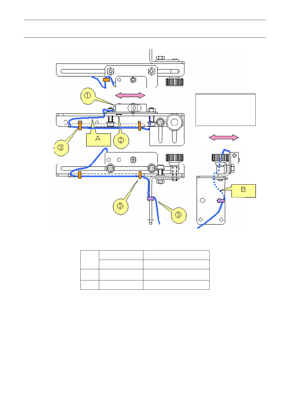
The cable should have
an allowance when the
movable part is moved
in the direction indicated
b
an arrow mark.
Figure 5-6-2-2 Front Reference: Right Sensor, Rear Reference: Left Sensor
40092568 LEFT_SENSOR_ASM
c
40092567 RIGHT SENS CABLE ASM
d
SL4031291SC
SCREW M3×L12
e
EA9500B0000 CABLE_BAND
<Adjusting the sensitivity>
1) Make an adjustment so that a (matte) black glass epoxy PWB placed on the transport path
can be detected.
2) Place a (matte) black glass epoxy PWB under the sensor and rotate the sensitivity
adjustment knob of the sensor counterclockwise. Then gradually rotate it clockwise up to the
position at which the specified PWB is detected.
∗ If any black glass epoxy PWB is not available, use the PWB having the darkest color of
those to be used.

 Loading...


