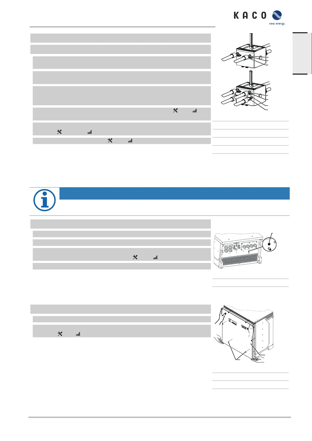
↻ DC cable is configured.
↻ DC input plate pulled back from the connection side. [approx. 20 cm]
NOTE:For installation of the DC cables, use a torque wrench as well as the in-
cluded open-ended wrench for counter-resistance.
1 Pre-fit DC cable pair with the pre-installed screw and counternut onto the DC+
and DC busbar of the DC switch.
2 Option for 2 cable pairs: Insert spacer sleeve between 2 DC cables and pre-as-
semble in pairs with the provided screws and counternuts onto the DC+ and DC
busbar of the DC switch.
3 Slide the DC input plate up onto the housing base and secure. [ T_30 / 6
Nm]
4 Secure the screws and counternuts onto the DC+ and DC busbar of the DC
switch. [ W_16/17] / 30 Nm ]
5 Tighten the cable screw fitting. [ W_46 / 7.5 Nm]
» Component is electrically connected. Continue with the installation in the in-
verter.
Fig.21: Fit DC cables to switch
1 Nut
2 Lock washer
3 Spacer sleeve
4 Fixing screw
7.7 Creating equipotential bonding
NOTE
Depending on the local installation specifications, it may be necessary to earth the device with a second
ground connection. To this end, the threaded bolt on the underside of the device can be used.
↻ The device has been installed on the mount.
1 Strip the insulation from the equipotential bonding cable.
2 Furnish the stripped cable with an M8 ring cable lug.
3 Lay the cable for equipotential bonding onto the grounding point and attach
with an additional M8 nut and lock washer [ W_17/ 10 Nm].
4 Check that the connected cable is fitted securely.
» The housing is included in the equipotential bonding.
Fig.22: Additional grounding point
1 Earthing bolt
7.8 Sealing the connection area
↻ The grid connection has been prepared.
1 Lift the housing cover onto the housing and loosely tighten the fastening screws.
2 Secure the housing cover by tightening all 6 screws in a diagonally opposite se-
quence [ T_25/ 4.8 Nm].
» The device has been mounted and installed.
» Put the device into operation.
Fig.23: Closing the housing cover
1 Housing cover
3 Screws
KACO blueplanet 87.0 TL3 KACO blueplanet 92.0 TL3 KACO blueplanet 110 TL3 KACO blueplanet 125 TL3
KACO blueplanet 137 TL3 KACO blueplanaet 150 TL3
Page 25
EN
 Loading...