301ENGINE
-
WORK
ON
THE
INDIVIDUAL
PARTS
135
Installinl
the
rocker
arm
200203-11
Checkinl
the
clutch
200176-01
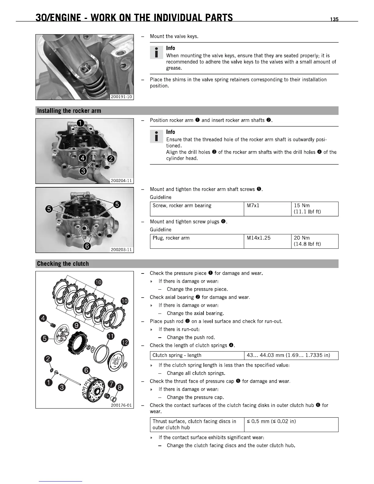
- Mount the valve
keys.
•
Info
I
When
mounting the valve
keys,
ensure that they are seated properly; it is
recommended
to
adhere the valve
keys
to the valves with a small amount
of
grease.
- Place the shims in the valve spring retainers corresponding to their installation
position.
- Position rocker
arm.
and insert rocker arm shafls
•.
•
Info
I Ensure that the threaded hole of the rocker arm shaft is outwardly posi-
tioned.
Align the drill
holes.
of the rocker
arm
shafts with the drill
holes.
of the
cylinder head.
- Mount and tighten the rocker
arm
shaft screws
•.
Guideline
Screw, rocker arm bearing
M7x1
- Mount and tighten screw
plugs
•.
Guideline
Plug, rocker
arm
M14x1.25
- Check the pressure piece
0 for damage and wear.
•
If
there is damage or wear:
- Change the pressure piece.
- Check axial
bearing.
for damage and wear.
•
If
there is damage or wear:
- Change the axial bearing.
- Place push
rod
•
on
a level surface and check for run-out.
•
If
there is run-out:
- Change the push rod.
- Check the length
of
clutch springs e.
15
Nm
(ll.llbfft)
20
Nm
(14.8
Ibf
ft)
1 Clutch spring
-length
143
...
44.03
mm
(1.69
...
1.7335
in)
•
If
the clutch spring length is
less
than the specified value:
- Change all clutch springs.
- Check the thrust face
of
pressure
cap.
for damage and
wear.
•
If
there is damage or wear:
- Change the pressure cap.
- Check the contact surfaces of the clutch facing disks in outer clutch
hub.
for
wear.
Thrust surface, clutch facing discs in
outer clutch hub
S
0.5
mm
(S
0.02
in)
•
If
the contact surface exhibils significant wear:
- Change the clutch facing discs and the outer clutch hub.
301ENGINE
-
WORK
ON
THE
INDIVIDUAL
PARTS
135
Installinl
the
rocker
arm
200203-11
Checkinl
the
clutch
200176-01
- Mount the valve
keys.
•
Info
I
When
mounting the valve
keys,
ensure that they are seated properly; it is
recommended
to
adhere the valve
keys
to the valves with a small amount
of
grease.
- Place the shims in the valve spring retainers corresponding to their installation
position.
- Position rocker
arm.
and insert rocker arm shafls
•.
•
Info
I Ensure that the threaded hole of the rocker arm shaft is outwardly posi-
tioned.
Align the drill
holes.
of the rocker
arm
shafts with the drill
holes.
of the
cylinder head.
- Mount and tighten the rocker
arm
shaft screws
•.
Guideline
Screw, rocker arm bearing
M7x1
- Mount and tighten screw
plugs
•.
Guideline
Plug, rocker
arm
M14x1.25
- Check the pressure piece
0 for damage and wear.
•
If
there is damage or wear:
- Change the pressure piece.
- Check axial
bearing.
for damage and wear.
•
If
there is damage or wear:
- Change the axial bearing.
- Place push
rod
•
on
a level surface and check for run-out.
•
If
there is run-out:
- Change the push rod.
- Check the length
of
clutch springs e.
15
Nm
(ll.llbfft)
20
Nm
(14.8
Ibf
ft)
1 Clutch spring
-length
143
...
44.03
mm
(1.69
...
1.7335
in)
•
If
the clutch spring length is
less
than the specified value:
- Change all clutch springs.
- Check the thrust face
of
pressure
cap.
for damage and
wear.
•
If
there is damage or wear:
- Change the pressure cap.
- Check the contact surfaces of the clutch facing disks in outer clutch
hub.
for
wear.
Thrust surface, clutch facing discs in
outer clutch hub
S
0.5
mm
(S
0.02
in)
•
If
the contact surface exhibils significant wear:
- Change the clutch facing discs and the outer clutch hub.
 Loading...