301ENGINE
ASSEMBLY
Installinllha
clutch
discs
8--+HfHl
400535-10
- Block the clutch hub
and
primary gear using special
tool
•.
I
Gear
quadrant
(80029004000)
('r
p.
262)
- Mount and tighten the nut.
Guideline
Nut, pri mary gear M20LHx1.5
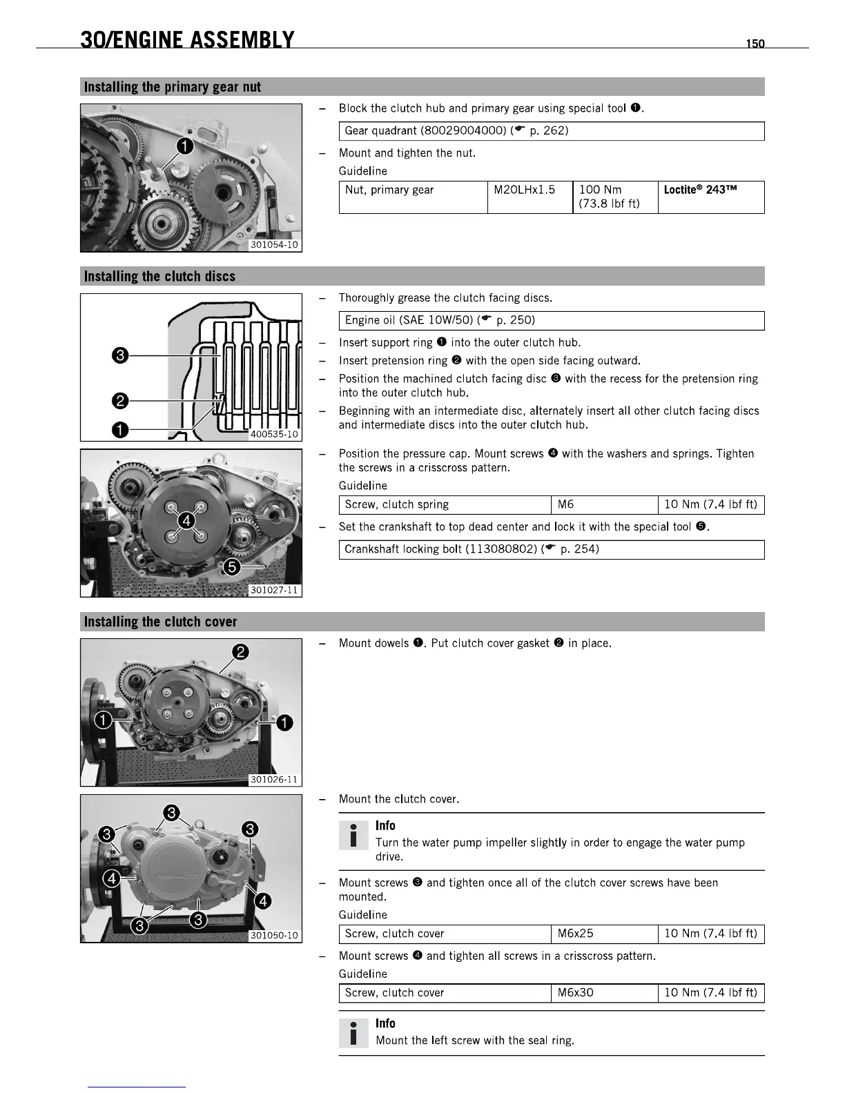
- Thoroughly
grease
the clutch facing discs.
I Engine oil
(SAE
lOW/50) (r
p.
250)
100
Nm
(73.8
Ibf
It)
- Insert support ring 0 into the outer clutch hub.
- Insert pretension
ring.
with the
open
side facing outward.
150
Lactile- 243'"
- Position the machined clutch facing
disc.
with the recess for the pretension ring
into the outer cl utch hub.
- Beginning with
an
intermediate disc, alternately insert all other clutch facing discs
and intermediate discs into the outer clutch hub.
- Position the pressure cap. Mount screws
I»
with the
washers
and
springs. Tighten
the
screws
ina
crisscross
pattern.
Guideline
I Screw, clutch spring I M6
110
Nm
(7.4
Ibf
It)
I
- Set the crankshaft to top
dead
center
and
lock
it
with the special
tool
•.
I Crankshaft locking bolt
(113080802)
(r
p.
254)
- Mount dowels
•.
Put clutch cover
gasket.
in
place.
- Mount the clutch cover.
•
Info
I Turn the water pump impeller slightly
in
order to
engage
the water pump
drive.
- Mount
screws.
and
tighten once all of the clutch cover screws
have
been
mounted.
Guideline
I Screw, clutch cover
I M6x25
110
Nm
(7.4
Ibf
It)
I
- Mount
screws.
and
tighten all screws
in
a crisscross pattern.
Guideline
I Screw, clutch cover I M6x30
110
Nm
(7.4
Ibf
It)
I
•
Info
I Mount the left screw with the
seal
ring.
301ENGINE
ASSEMBLY
Installinllha
clutch
discs
8--+HfHl
400535-10
- Block the clutch hub
and
primary gear using special
tool
•.
I
Gear
quadrant
(80029004000)
('r
p.
262)
- Mount and tighten the nut.
Guideline
Nut, pri mary gear M20LHx1.5
- Thoroughly
grease
the clutch facing discs.
I Engine oil
(SAE
lOW/50) (r
p.
250)
100
Nm
(73.8
Ibf
It)
- Insert support ring 0 into the outer clutch hub.
- Insert pretension
ring.
with the
open
side facing outward.
150
Lactile- 243'"
- Position the machined clutch facing
disc.
with the recess for the pretension ring
into the outer cl utch hub.
- Beginning with
an
intermediate disc, alternately insert all other clutch facing discs
and intermediate discs into the outer clutch hub.
- Position the pressure cap. Mount screws
I»
with the
washers
and
springs. Tighten
the
screws
ina
crisscross
pattern.
Guideline
I Screw, clutch spring I M6
110
Nm
(7.4
Ibf
It)
I
- Set the crankshaft to top
dead
center
and
lock
it
with the special
tool
•.
I Crankshaft locking bolt
(113080802)
(r
p.
254)
- Mount dowels
•.
Put clutch cover
gasket.
in
place.
- Mount the clutch cover.
•
Info
I Turn the water pump impeller slightly
in
order to
engage
the water pump
drive.
- Mount
screws.
and
tighten once all of the clutch cover screws
have
been
mounted.
Guideline
I Screw, clutch cover
I M6x25
110
Nm
(7.4
Ibf
It)
I
- Mount
screws.
and
tighten all screws
in
a crisscross pattern.
Guideline
I Screw, clutch cover I M6x30
110
Nm
(7.4
Ibf
It)
I
•
Info
I Mount the left screw with the
seal
ring.
 Loading...