30/ENGINE - WORK ON INDIVIDUAL PARTS 116
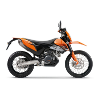
19.7Checking crankshaft run-out at bearing pin
300132-10
– Position the crankshaft on a roller block.
– Rotate the crankshaft slowly.
– Check the crankshaft run-out at both bearing pins.
Crankshaft run-out at bearing pin ≤ 0.10 mm (≤ 0.0039 in)
» If the crankshaft run-out at the bearing pin is greater than the specified value:
– Align the crankshaft.
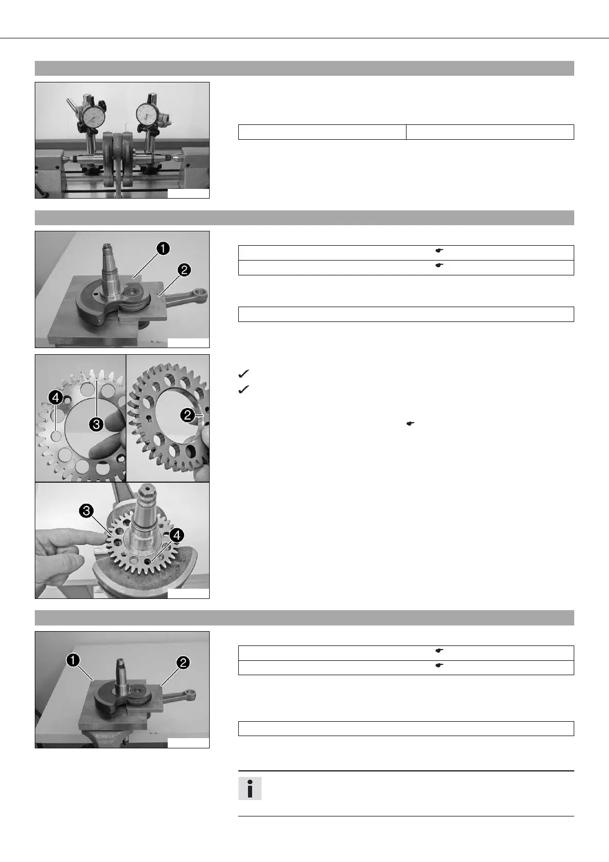
19.8Installing balancer shaft drive wheel
300145-10
– Fix the crankshaft with special tools and in the vise.
Upper part, pressing-out tool (75029047050) ( p. 217)
Under part, pressing-out tool (75029047051) ( p. 217)
– Warm the drive wheel.
Guideline
100 °C (212 °F)
300159-10
– Place the drive wheel on the crankshaft.
The dowel of the crankshaft must fit in the drill hole .
The side of the drive wheel with the punch mark must be visible after
assembly, and the side with the bevel must be in contact with the
crankweb.
– Install the crankshaft bearing inner ring. ( p. 116)
19.9Installing crankshaft bearing inner ring
300134-10
– Fix the crankshaft with special tools and in the vise.
Upper part, pressing-out tool (75029047050) ( p. 217)
Under part, pressing-out tool (75029047051) ( p. 217)
– Push on the compensation shim.
– Heat the special tool. Install the inner bearing race.
Guideline
120 °C (248 °F)
– Repeat the operation on the opposite side.
– Make sure that the new inner ring is flush installed.
Info
After changing the crankshaft bearing, measure the axial clearance of the
crankshaft.
 Loading...