U20-3, U25-3 WSM Hydraulic system (Mechanism section)
IV-M-19
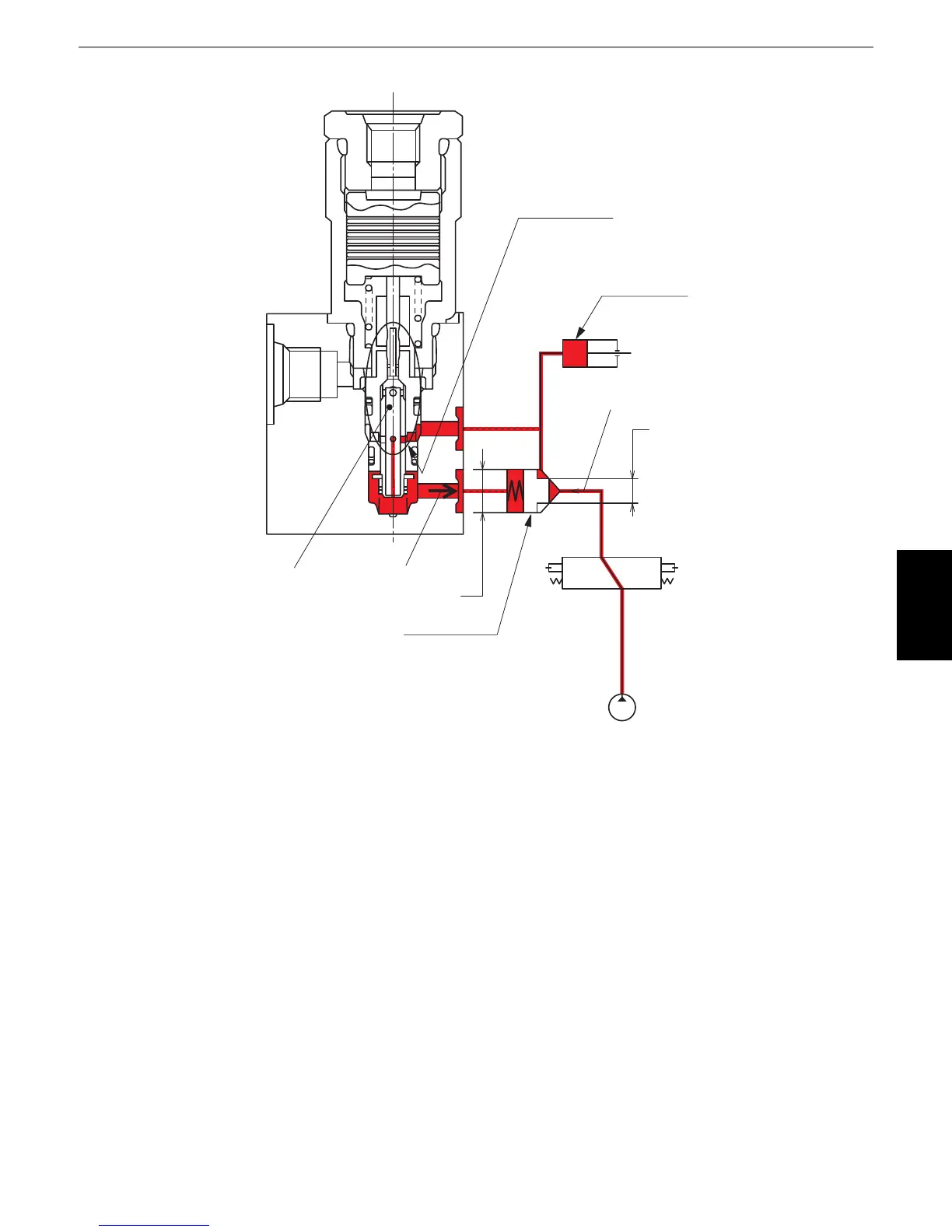
Details of the anti-drift valve operation
The oil from the pump comes pushing through the anti-drift poppet into the boom cylinder. The oil also
passes through the poppet "d" and reaches behind the anti-drift poppet.
The power balance at this time is expresses as P
1 ✕ A1 > P2 ✕ A2.
Where P
1: Pressure of the oil from the pump
P
2: Pressure applied behind the anti-drift poppet (P1 > P2 because of the throttling effect of poppet
"d")
A
1: Area exposed to the pressure P1
A2: Area exposed to the pressure P2
The anti-drift poppet shifts to the left in the above figure.
A
1 < A2 but P1 >> P2, Thus we have P1 ✕ A1 > P2 ✕ A2.
Poppet "d"
Anti-drift poppet
Boom cylinder
Throttling effect
A
2
P2
P1
A1
 Loading...


