U20-3, U25-3 WSM Electrical system (Service section)
V-S-17
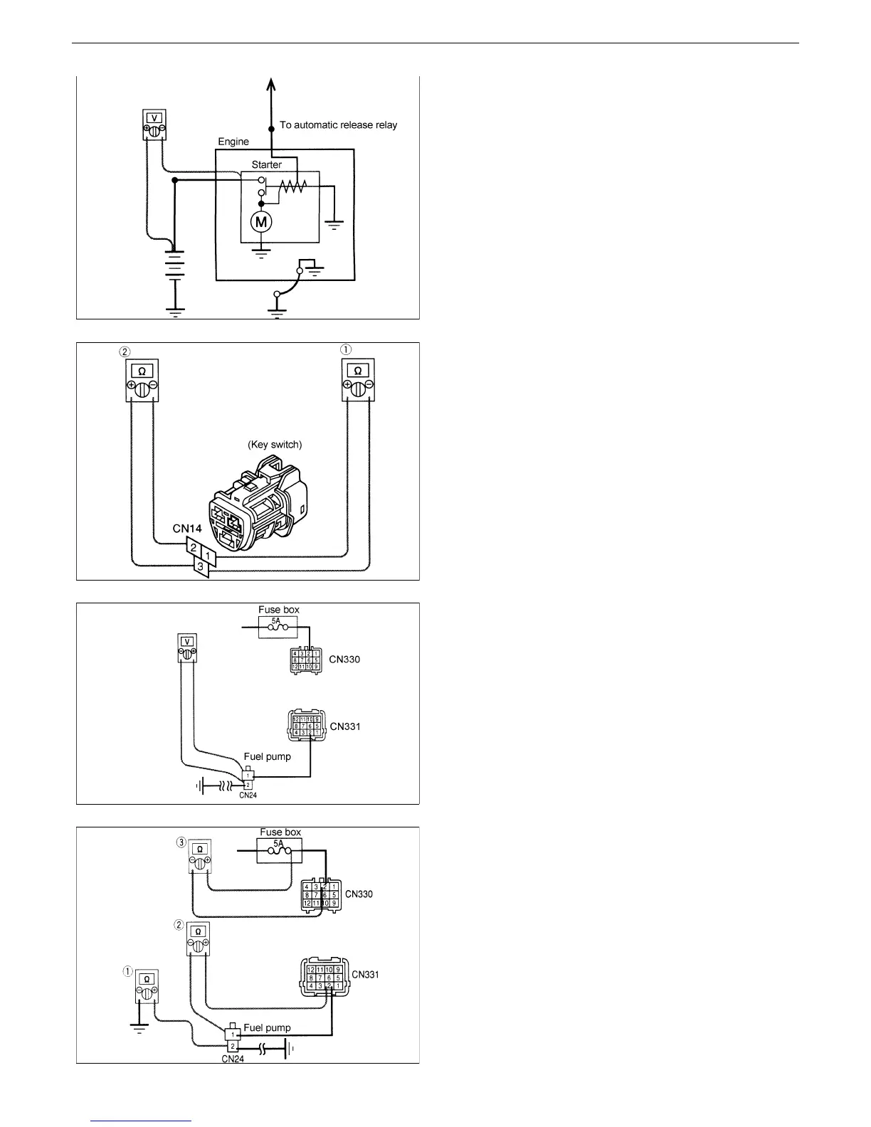
Fig.7
Fig.8
Fig.9
Fig.10
3. Continuity check (Fig.7)
2
Key switch: OFF
2
Check for continuity between the starter B
terminal and battery (+) terminal.
[6] Key switch
2 Disconnect the key switch and the key
switch coupler CN14.
1. Set the key switch to the ON position (key right
1st step) and check for continuity between (1)
and (3).
2. Hold the key switch in the starting position (key
right 2nd step) and check for continuity
between (2) and (3).
Continuity :The key switch is normal.
No continuity :The key switch is faulty.
[7] Fuel pump coupler
1. Measuring the voltage of the fuel pump
coupler (Fig.9)
2 Disconnect the fuel pump coupler CN24.
2 Key switch: ON
2 Measure the voltage between (1) and (2) of
the coupler CN24.
12 V : The fuel pump is faulty.
Other than 12 V: Check for continuity.
(Fig.10)
2. Continuity check (Fig.10)
2 Key switch: ON
2 Disconnect the coupler.
(1) Check for continuity between the fuel sensor
coupler CN24-(2) and body earth.
(2) Check for continuity between the fuel sensor
coupler CN24-(1) and coupler CN24-(2).
(3) Check for continuity between the 5A fuse and
coupler CN330-(2).
 Loading...


