U20-3, U25-3 WSM Electrical system (Service section)
V-S-27
Fig.38
Fig.39
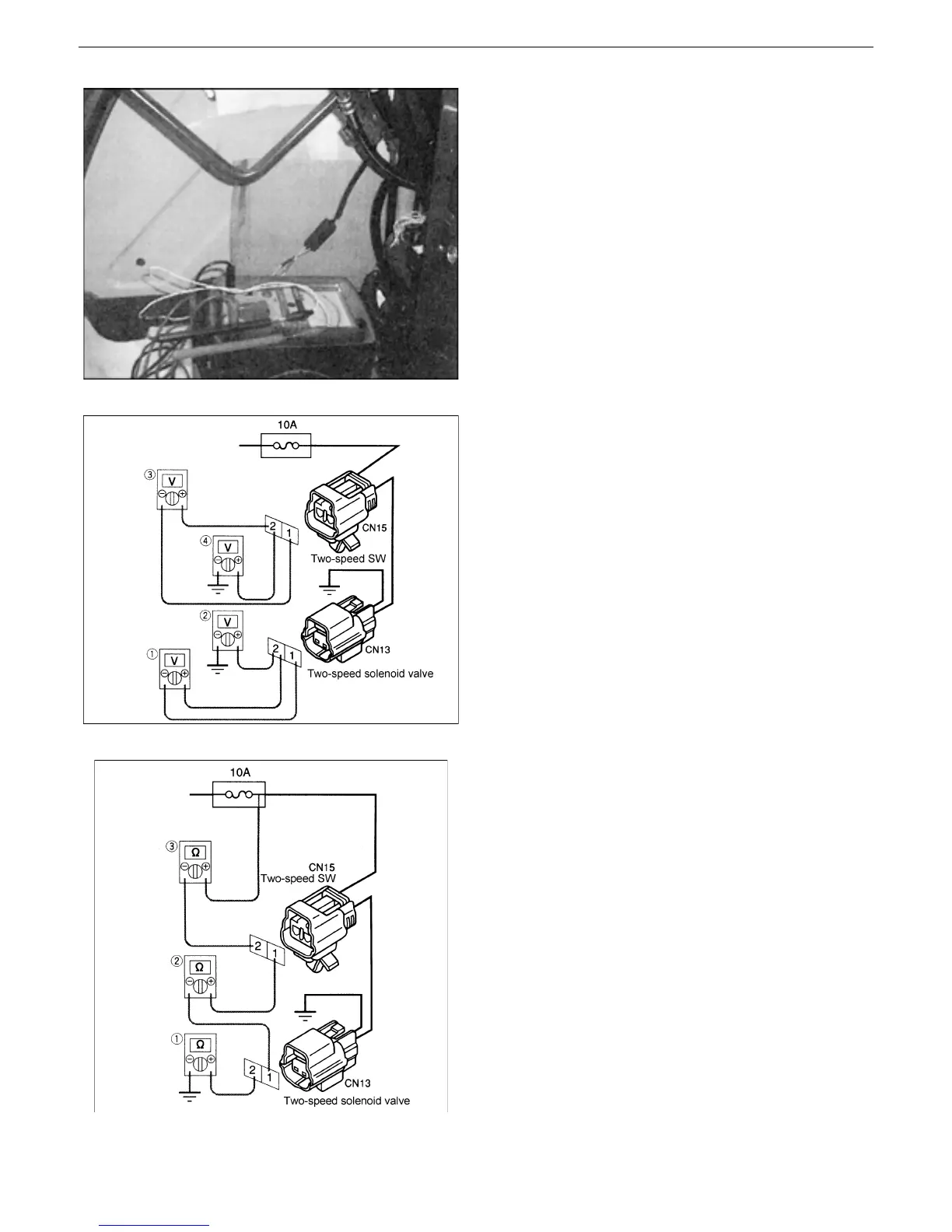
Fig.40
6. Inspection of lever lock switch (Fig.38)
Key switch: OFF
Turn ON/OFF the lever lock switch by moving
the unload lever of the right control lever and
check if the pointer of the tester shakes.
Shaking : Normal
Not shaking: Faulty
* In the case of the two-speed switch, use the
speed-up pedal.
7. Check if a voltage is applied to the two-speed
solenoid valve and two-speed switch coupler.
• Disconnect the coupler.
• Key switch: ON
(1) Measure the voltage between the solenoid
valve coupler CN13-(1) and (2).
(2) Measure the voltage between the solenoid
valve coupler CN13-(2) and body earth.
(3) Measure the voltage between the two-
speed switch coupler CN15-(1) and (2).
(4) Measure the voltage between the solenoid
valve coupler CN15-(2) and body earth.
8. Continuity check (Fig.40)
Disconnect the coupler from the part.
(1) Check for continuity between the CN13-(2)
and body earth.
(2) Check for continuity between the CN13-(1)
and CN15-(2).
(3) Check for continuity between the CN15-(2)
and body earth.
 Loading...


