U20-3, U25-3 WSM Hydraulic system (Service section)
IV-S-140
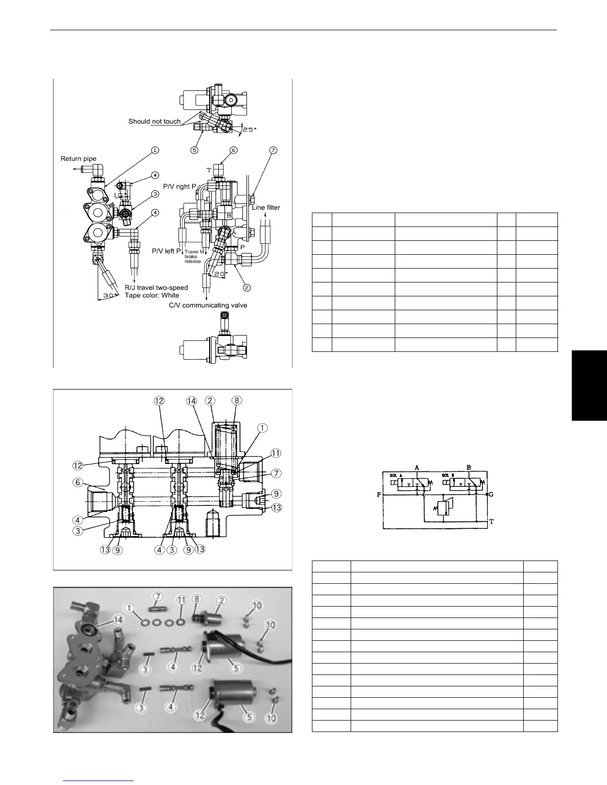
i. Other hydraulic valve
[1] Selector valve
Cross sectional view of selector valve
Disassembling the selector valve
1) Reassembling procedure:
1. Tightening torque of hydraulic adapter
G1/4 : 24.5~29.4N⋅m (2.5~3.0kgf⋅m)
G3/8 : 49.0~53.9N⋅m (5.0~5.5kgf⋅m)
* For the mounting direction and angle of the
hydraulic adapter, refer to the figure to the left.
2. Tightening torque of valve assembly (selector):
48.1~55.9 N⋅m (4.9~5.7 kgf⋅m)
Parts list
Tightening torque of hex socket bolt (10):
3.92 N⋅m (0.4 kgf⋅m)
Relief valve set pressure: 3.9 MPa (40 kgf/cm
2
)
Hydraulic circuit diagram
Parts list
No. Part No. Part name Q'ty Remarks
1RB411-6191Δ
Valve assembly (selector)
1
2 RC411-63841 Pipe joint (T, F2-F3) 1 P
3 RP201-61892 Pipe joint (L, G1/4- G1/4) 1 B
4 68591-63231 Washer based elbow 2 A⋅B
5 RC101-63831 T pipe joint (F2) 1 B
6RB411-6391Δ
Elbow pipe joint (G3/8-13)
1T
04810-00110 O-ring 4
A
⋅
B for 1/4
04810-00140 O-ring 2
P
⋅
T for 3/8
7 01125-61020 Bolt 2
M10
×
1.5 7T
No. Part name Q'ty
1Shim 3
2 Cover spring 1
3Spring 2
4Spool 2
5 Solenoid 2
6Body 1
7Plunger 1
8Spring 1
9 Flanged plug 3
10 Hex socket bolt 6
11 Flat washer 1
12 O-ring 2
13 O-ring 3
14 O-ring 1
 Loading...


