U20-3, U25-3 WSM Electrical system (Mechanism section)
V-M-8
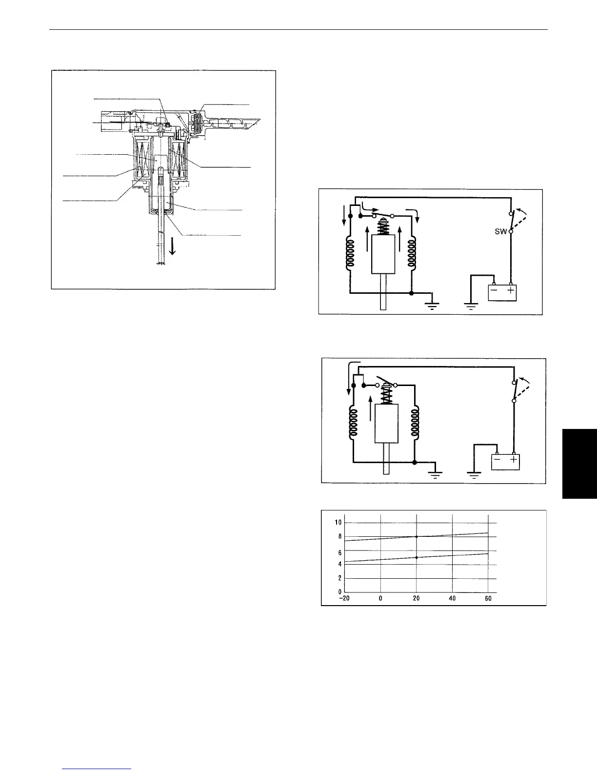
(2)Engine stop solenoid
1) Structure
Specifications
1. Rated voltage : DC12V
2. Rated ampere
Pull-in coil : 32A / DC12V
Hold coil : 77A / DC12V
at 20°C
3. Resistance
Pull-in coil :
Ω
Hold coil : Ω
2) Circuit and its function
The engine stop solenoid circuit is as shown at
left.
Turn the key switch to the ON position, and the
battery current flows both to the pull-in coil and
the holding coil. These coils are excited to attract
and lift the plunger.
Now the fuel injection pump is ready to get the
engine started.
Being attracted upward, the plunger pushes and
opens the contact, which discontinues the cur-
rent flow to the pull-in coil.
With the current still flowing to the holding coil,
the plunger stays in this position.
Turn the key switch to the OFF position, and the
current flow to the holding coil is also interrupted.
By the force of the return spring, the plunger
comes back to the original position. By so doing,
the fuel injection pump will be back to the
engine-off status.
Suicide switch
filter
plunger
holding coil
Pull-in coil
spring
plunger
oil seal
Holding coil
Pull-in coil
Holding coil
Pull-in coil
Solenoid voltage
Tem p.
 Loading...


