U20-3, U25-3 WSM Hydraulic system (Mechanism section)
IV-M-47
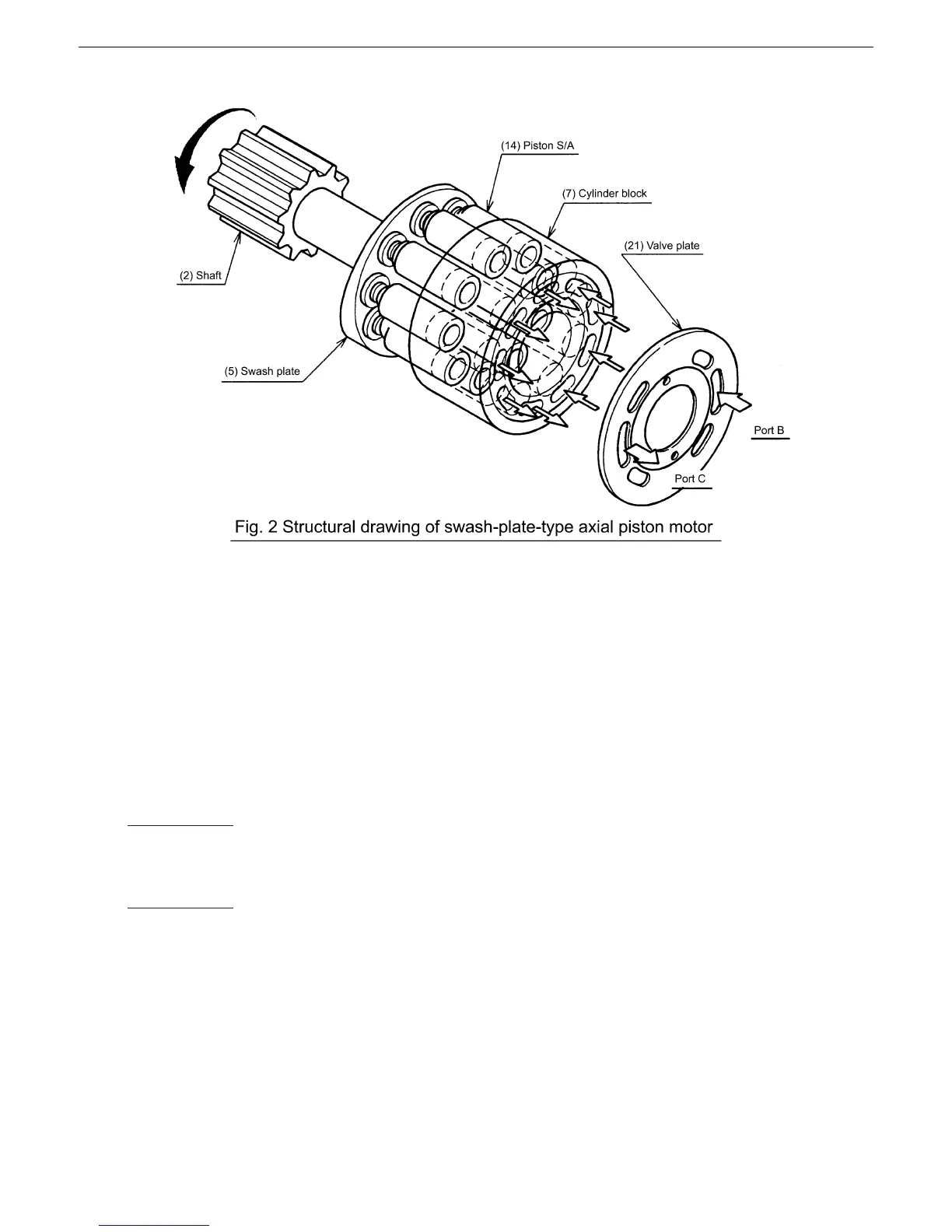
b. Operating principle of motor
The cylinder block (7) incorporates nine piston S/As (14).
The end face of the cylinder block (7) is in contact with the valve plate (21) having two semicircular ports
B and C (high-low change valve).
When the high pressure oil (pressure P) is supplied to the port B, it presses the swash plate (5) with a
force of “F = P·A” (A: Pressure-applied area of piston) per piston S/A (14). The piston S/A (14) receives a
reaction force against this force, which produces a turning force (Ft). The sum of the turning forces
produced through the piston S/As (14) on the high pressure side makes the cylinder block (7) rotate,
which torque is transmitted to the shaft (2) through the splines, making the shaft (2) rotate.
The output torque and revolution of the piston motor obtained based on the above-mentioned operating
principle are determined by the supplied pressure (P) and the supply flow rate (Q) and calculated from the
following expression.
T =
N =
P × D × ηm
Q × 10
3
× ηv
2 × π × 10
2
D
T : Output torque (kgf-m)
N : Revolutions (rpm)
P : Working pressure (kgf/cm
2
)
Q : Supply flow rate (L / min)
D : Theoretical displacement (cc/rev)
ηm : Mechanical efficiency
ηv : Volumetric efficiency
 Loading...


