U20-3, U25-3 WSM Hydraulic system (Service section)
IV-S-21
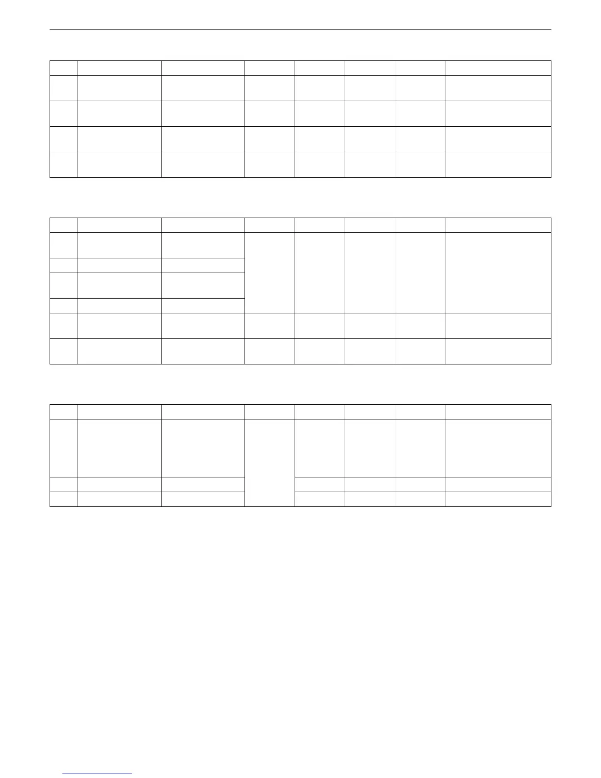
[2] Main relief valve (at the measurement port on the machine)
[3] Overload relief valve (bench data)
[4] Overload ralief valve (at the measurement port on the machine)
No. Valve location Operating work Unit U20-3 U25-3 Remarks
1
P1
Main relief valve
Bucket crowd
MPa
kgf/cm
2
22.1
225
22.1
225
2
P2
Main relief valve
Arm crowd or
dump
MPa
kgf/cm
2
22.1
225
22.1
225
3
P3
Main relief valve
Swing Left or
Right
MPa
kgf/cm
2
21.1
215
17.6
180
4
Pilot primary
pressure
All pilot lines
MPa
kgf/cm
2
4.1 ± 0.5
42 ± 5
4.2 ± 0.5
43 ± 5
No. Valve location Operating work Unit U20-3 U25-3 Remarks
5 Control valve
Boom up
Boom down
MPa
kgf/cm
2
24
245
24
245
at 29 L/min
6 Control valve Bucket crowd
7 Control valve
Arm dump
Arm crowd
8 Control valve Dozer down
9 Control valve Dozer up
MPa
kgf/cm
2
24
245
24
245
at 18 L/min
10 Swivel motor Swivel, R & L
MPa
kgf/cm
2
19.6
200
16.2
165
No. Valve location Operating work Unit U20-3 U-25-3 Remarks
5
6
7
8
Control valve
Boom up, down
Arm dump, crowd
Bucket dump,
crowd
Dozer down
MPa
kgf/cm
2
9 Control valve Dozer up
10 Swivel motor Swivel R & L
+1.0
-0.5
+10
-5
+1.0
-0.5
+10
-5
 Loading...


