U20-3, U25-3 WSM Hydraulic system (Service section)
IV-S-31
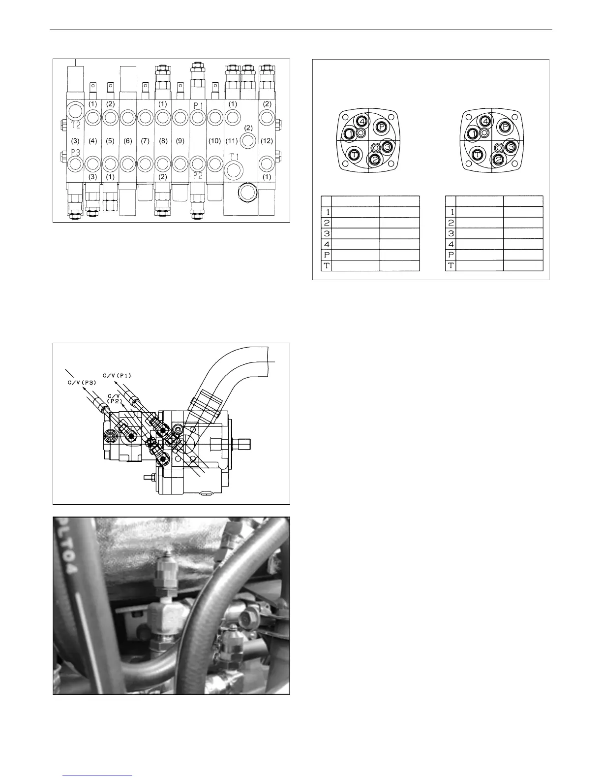
Control valve section layout
(1) Rod (2) Bottom
(3) Communicating valve (4) Dozer
(5) Swing (6) Swivel
(7) Spare (8) Arm
(9) Travel left (10) Travel right
(11) Boom (12) Bucket
[2] Main relief valve pressure
Pump discharge side
Pilot valve hose routes
1) Measuring procedure
1. Remove the adaptor plug (1/8) of main pump
discharge side and connect thereto a pressure
gauge.
P1 Bucket, boom and travel right
P2 Arm, service port and travel left
P3 Swivel, swing and dozer
2. Start the engine. Check the circuit to be
measured for oil leak.
3. With the engine running at maximum rpm,
operate the lever to relieve the cylinder.
4. Repeat the pressure measurement 3 times,
obtain the average and adopt it as measured
value.
* Measure the pressure at oil temperature of
50±5°C.
Left pilot valve Right pilot valve
Left pilot valve Right pilot valve
Back Back
Front Front
Location
Swivel left
Arm dump
Swivel right
Arm tuck-in
Port P
Port T
Hose tape color
Red
Blue
Yellow
Green
No color
No color
Location
Bucket tuck-in
Boom down
Bucket dump
Boom up
Port P
Port T
Hose tape color
Pink
Sky-blue
Brown
Gray
No color
No color
}
{
 Loading...


