U20-3, U25-3 WSM Hydraulic system (Mechanism section)
IV-M-27
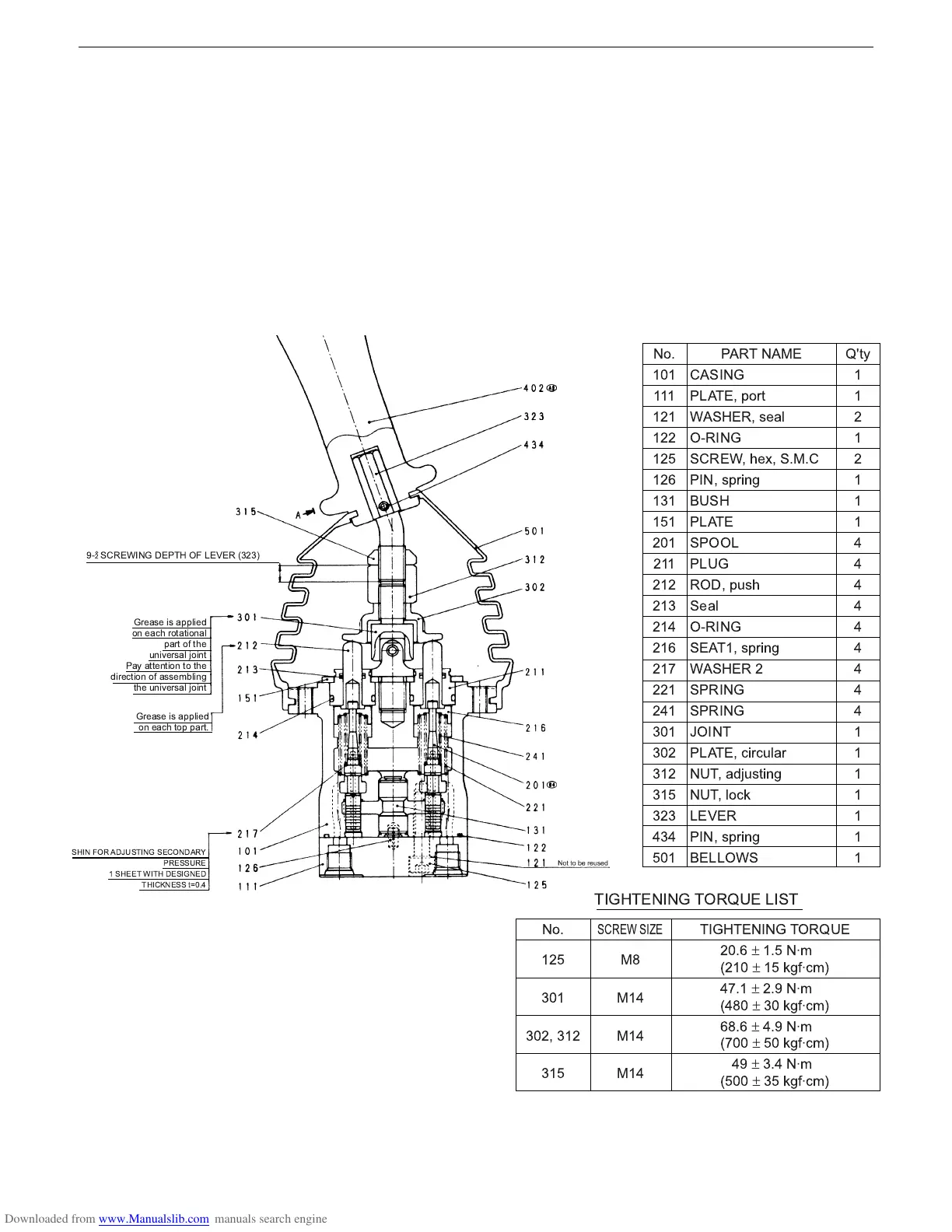
E.Pilot valve
a. Structure
The construction of pilot valve is shown in the sectional view (page 16). The casing has a vertical hole in
which a reducing valve is integrated.
The reducing valve consists of spool (201), secondary pressure setting spring (241), return spring (221),
spring washer (216) and washer 2 (217). The secondary pressure setting spring (241) has been factory-
adjusted to a converted secondary pressure of 0.5-1 MPa (depending on models). The spool (201) is kept
against the push rod (212) by the return spring (221).
Tilt the operating lever, and the push rod (212) is pressed down and the spring seat goes down too. This
affects the secondary pressure setting spring (241).
The oil inlet (primary pressure) port P and outlet (tank) port T are located at the casing (101) and port
plate (111). The secondary pressure is taken out of the ports 1, 2, 3 and 4.
!
!
" #
$
%
&
''#
! ()#
! '*
+
$,$
$$$
$%$
$%%
$%.
$%/
$0$
$.$
%,$
%$$
%$%
%$0
%$1
%$/
%$2
%%$
%1$
0,$
0,%
0$%
0$.
0%0
101
.,$
345
$
$
%
$
%
$
$
$
1
1
1
1
1
1
1
1
1
$
$
$
$
$
$
$
3!
$%.
0,$
0,% 0$%
0$.
6
7
$1
$1
$1
3!
%,/
±
$. 89
:%$,
±
$. *;8'9<
12$
±
%= 89
:17,
±
0, *;8'9<
/7/
±
1= 89
:2,,
±
., *;8'9<
1=
±
01 89
:.,,
±
0. *;8'9<
=% " > + :0%0<
(
'
;
#? )
5
(' ; 9@
#? )
(
'
> "&! "A
!
$ ""
B C,1
 Loading...


