U20-3, U25-3 WSM Electrical system (Service section)
V-S-16
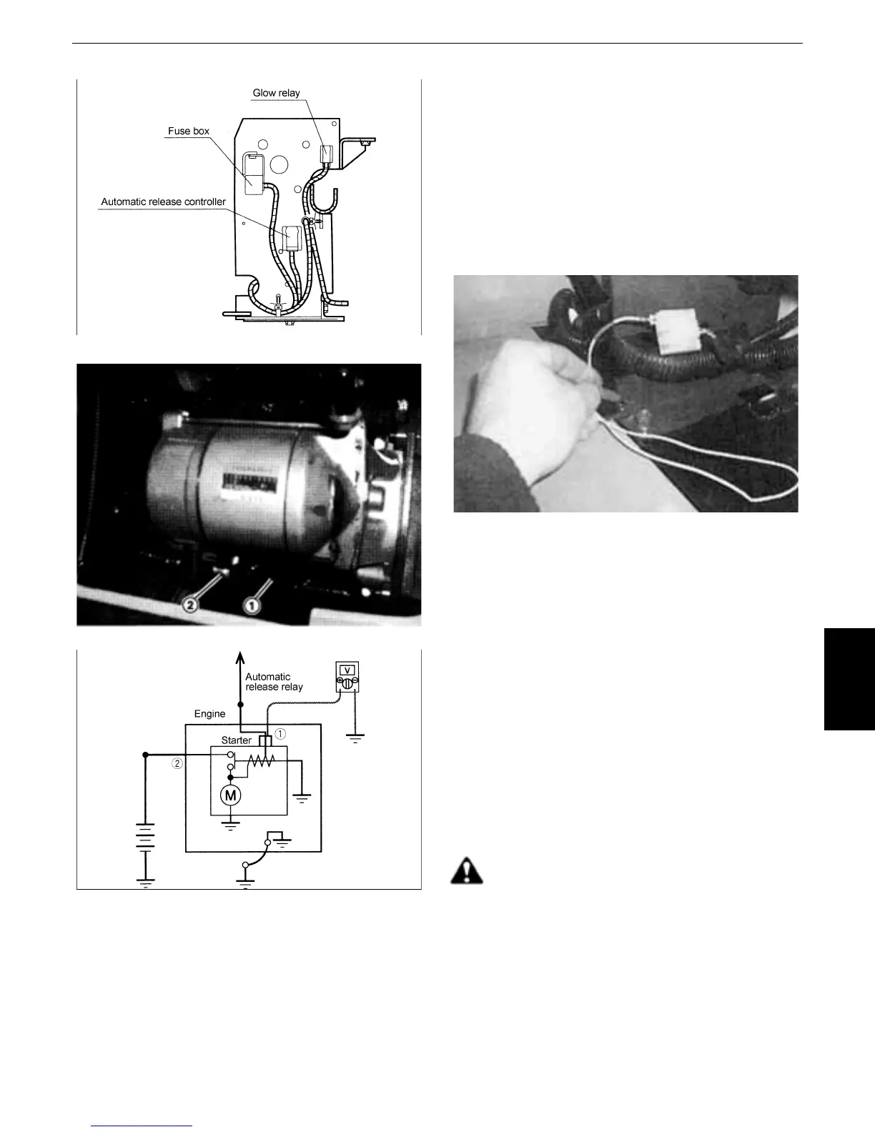
Fig. 5
Photo 2
Fig. 6
[4] Release controller
1. Disconnect the coupler CN310 from the
controller.
2. Body-earth the controller coupler CN310-(6),
set the key switch to the starting position and
check if the engine starts. (Photo 1)
Starting : The controller is faulty.
Not starting : The key switch is faulty or the
wire is broken.
Photo 1
[5] Starter motor
1. Check the B terminal of the starter motor for
looseness. Check the starter coupler CN37 for
disconnection. (Photo 2 (1))
2. Voltage check (Fig.6)
1) From the back, connect the lead of a tester
to the CN37 coupler terminal (1) connected
to the starter motor
2) Set the key switch to the starting position
and check if a voltage is applied to the
CN37 coupler terminal (1).
12 V : Check the continuity of
the harness.
Other than 12 V : The key switch is faulty.
Caution:
Note that the starter motor could run suddenly.
 Loading...


