U20-3, U25-3 WSM Hydraulic system (Mechanism section)
IV-M-32
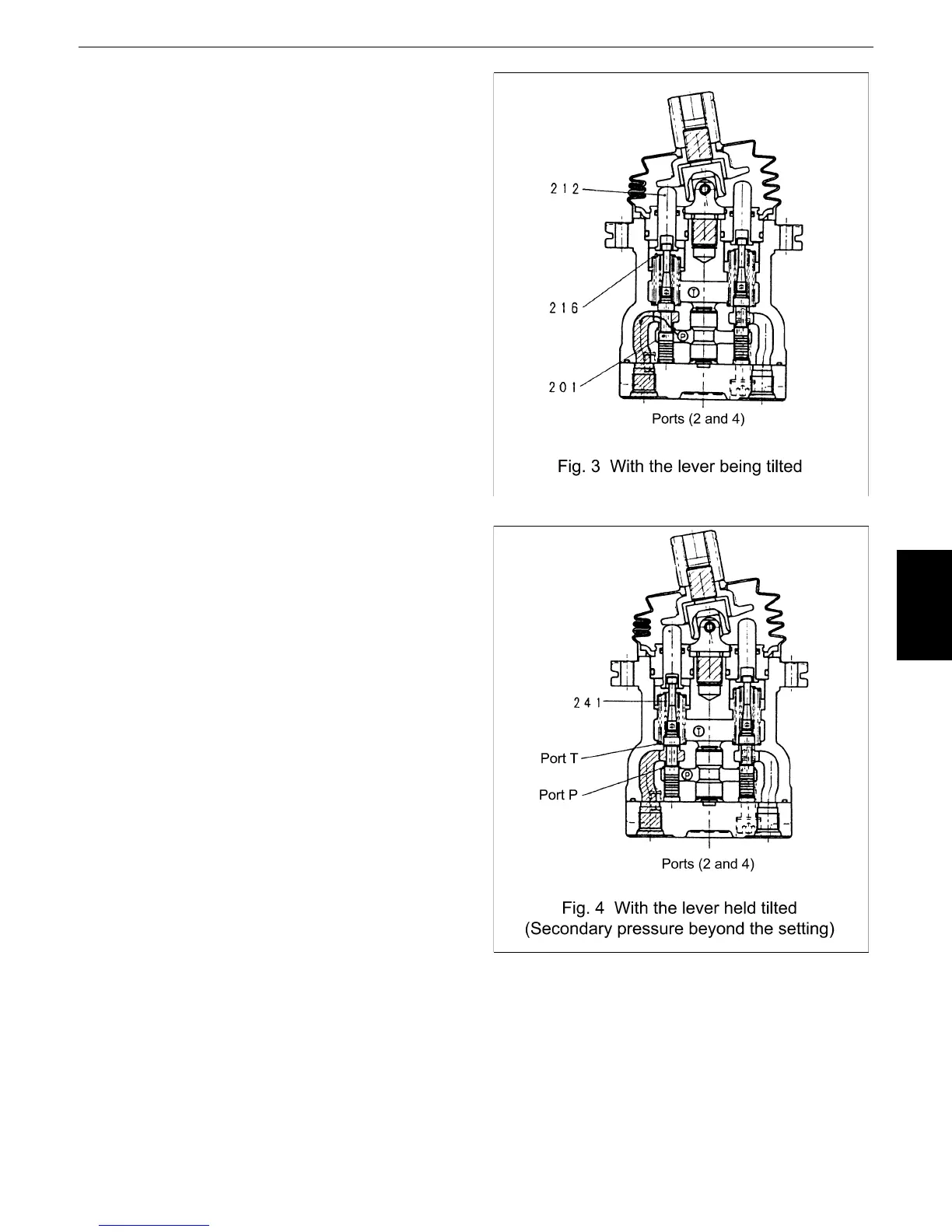
2) With the lever being tilted (See Fig. 3.)
When the lever is tilted and the push rod
(212) gives a stroke, the spool (201)
(spring seat (216)) lowers, which
interconnects the port P and output ports (2
and 4). In this state, the oil from the pilot
pump flows to the ports (2 and 4) and
produces a pressure.
3) With the lever held tilted (See Fig. 4.)
When the pressure at the ports (2 and 4)
has reached the level that corresponds to
the force of the spring (241), then the oil
pressure and spring force get balanced.
When the pressure at the ports (2 and 4)
has risen above the set level, the ports (2
and 4) and port P get closed, whereas the
ports (2 and 4) and port T get open. When
this pressure has dropped below the set
level, the ports (2 and 4) and port P get
open, whereas the ports (2 and 4) and port
T get closed.
4) With the lever too tilted (depending on the model)
On some models, if the lever is tilted beyond a certain angle, the spool top end comes in contact
with the push rod bottom. This means that the output pressure is being applied to the port P.
In another construction, the spring and its seat are integrated in the push rod. If the lever is tilted
beyond a certain angle, the spring comes in contact with the push rod bottom. The spring force in
turn affects the secondary pressure gradient. Then there will be contact between the push rod
bottom and the spring seat top end, which keeps the output pressure applied to the port P.
 Loading...


