U20-3, U25-3 WSM Electrical system (Service section)
V-S-21
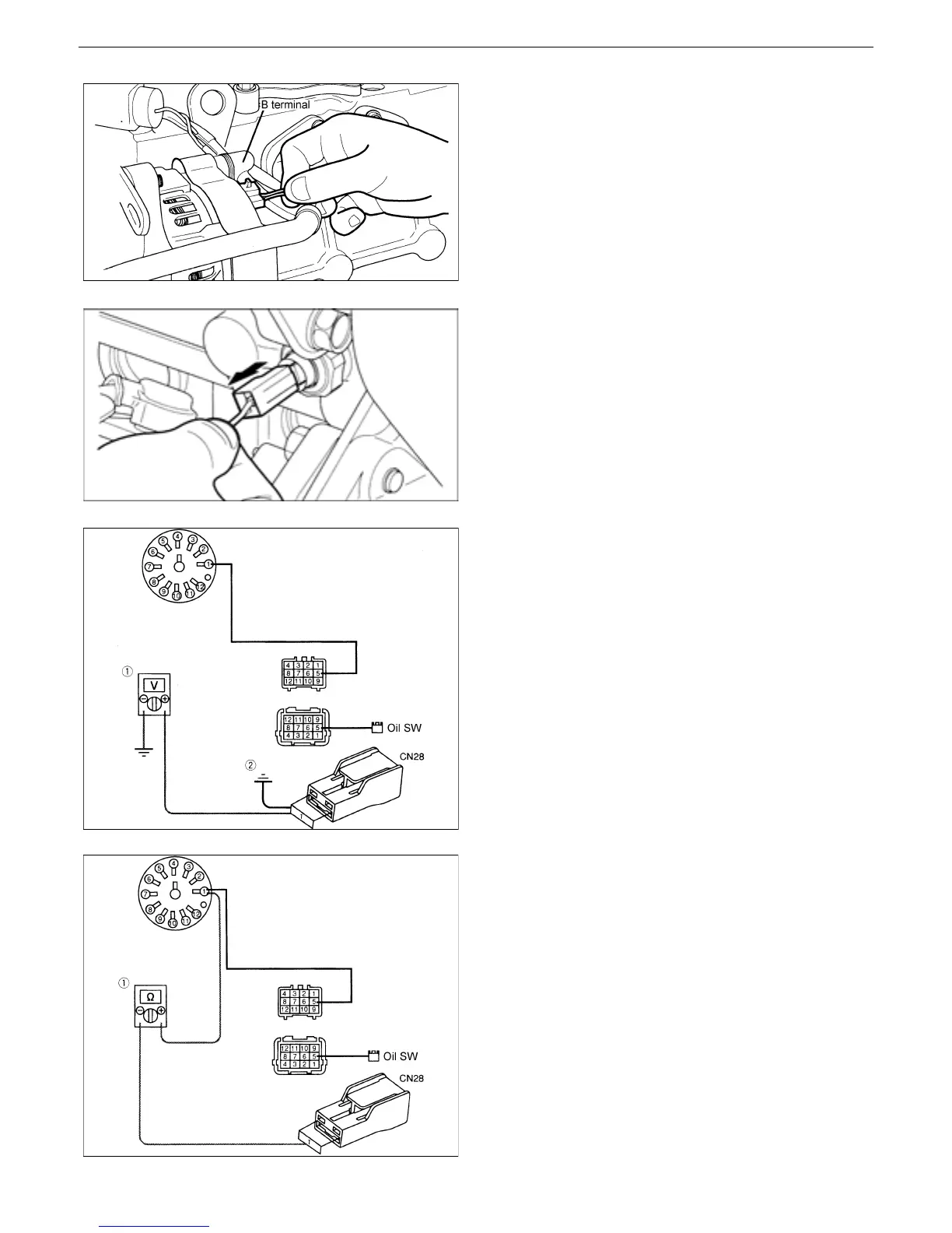
Fig.20
Fig.21
Fig.22
Fig.23
[10] Charge engine oil lamp
1. Check the alternator coupler and B terminal for
disconnection. (Fig.20)
2. Check the oil switch coupler CN28-(1) for
disconnection. (Fig.21)
3. Measuring the voltage of the oil switch coupler
CN28-(1) (Fig.22)
2 Disconnect the oil switch coupler CN28-(1).
2 Key switch: ON
(1)Measure the voltage of the oil switch
coupler CN28-(1).
12 V : Normal. Measure the
engine pressure.
Other than 12 V : Check for continuity.
(2)Body-earth the oil switch coupler CN28-(1).
Oil switch lamp
Light up :The oil switch is faulty.
Not light up :The harness is broken.
Check for continuity.
4. Continuity check (Fig.23)
2 Disconnect the meter coupler (large).
2 Key switch: OFF
Check for continuity between the oil switch
coupler CN28-(1) and meter coupler (large)
(1).
 Loading...


