U20-3, U25-3 WSM Machine body (Service section)
II-S-23
C.Upper structure
a. Lever and pedal
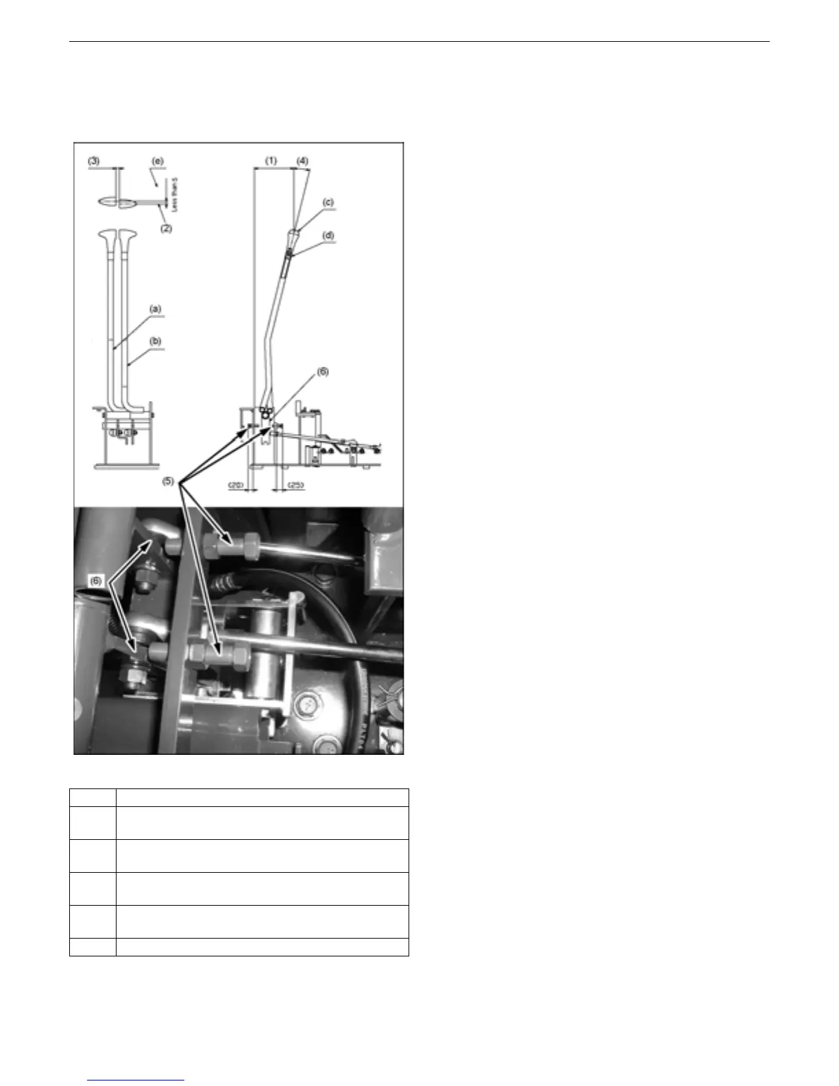
[1] Travel lever
1) Assembling procedure
1. Adjust the levers neutral positions, setup
directions and angles, referring to the
figure at left.
(1) Dimension between bracket front and
grip center
159mm (reference)
(2) Adjusting the travel levers neutral
positions
Keep the levers locked with a round
bar (10 dia.) and adjust the
misalignment between their tips within
5 mm.
(3) Clearance between right and left levers
11~17mm
(4) Setup angle of travel levers
14 degrees
(5) 01175-61045
Locking the stopper bolt
Bring the stay of the lever (travel, right/
left) in contact. Loosen the bolt by 90
degrees and lock it in this position.
Make sure the valve spool works all
over its stroke.
(6) With the levers at the neutral positions,
orient this part vertically.
(7) Move down the lever (lock, travel)
against the spring force to unlock the
travel mode.
(8) Adjust the rod to keep the travel levers
misalignment within the specified
range.
(9) Return the lever (lock, travel) back into
position to make sure the travel levers
get locked.
No.
(a)
Lever (travel, right)
RB419-6536Δ
(b)
Lever (travel, left)
RB419-6531Δ
(c)
Grip (travel)
RC101-65282
(d)
Cap
RC101-65292
(e) Misalignment between right sand left levers
 Loading...


