U20-3, U25-3 WSM Hydraulic system (Service section)
IV-S-33
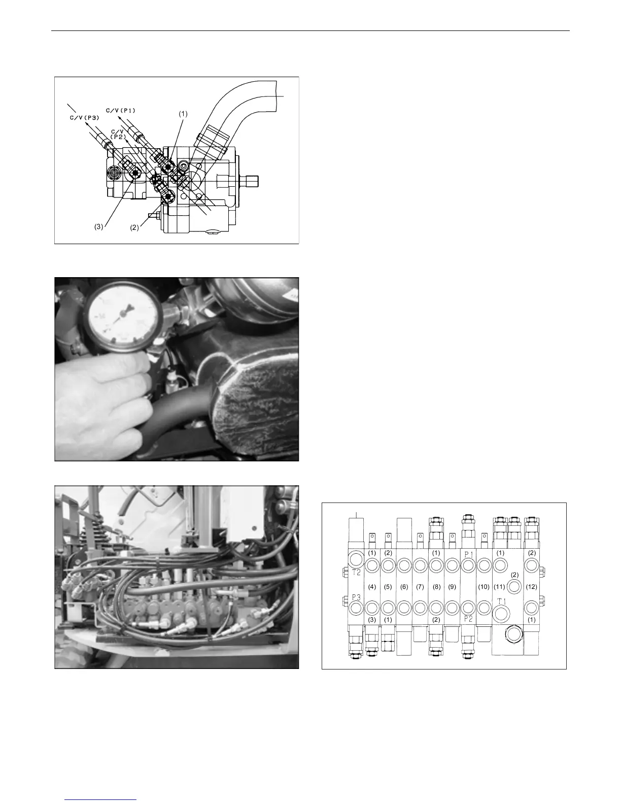
[3] Overload relief pressure
Pump discharge side
(1)C/V(P1) (2)C/V(P2) (3)C/V(P3)
1) Measuring procedure (in tucking in the
arm)
1. Remove the adaptor plug (2) (1/8) of main
pump discharge side and connect thereto a
pressured gauge.
2. Raise the set pressure of the main relief valve
(P2) approx. 0.98 MPa (10 kgf/cm
2
) higher
than that of the overload relief valve.
3. With the engine running at maximum rpm, tuck
in the arm, relieve the cylinder and measure
the set pressure.
4. Repeat the pressure measurement 3 times,
obtain the average and adopt it as measured
value.
5. After the measurement, return the pressure of
the main relief valve to the original set value.
* Measure the pressure at oil temperature of
50±5°C.
Control valve section layout
(1) Rod (2) Bottom
(3) Communicating valve (4) Dozer
(5) Swing (6) Swivel
(7) Spare (8) Arm
(9) Travel left (10) Travel right
(11) Boom (12) Bucket
(3)
 Loading...


