U20-3, U25-3 WSM Electrical system (Service section)
V-S-29
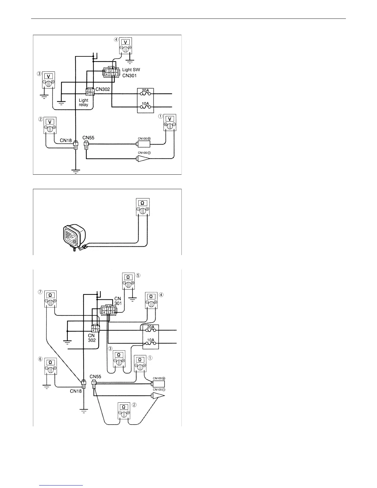
Fig.45
Fig.46
Fig.47
[15]working light
1. Measuring the voltage of the working light
• Key switch : ON
• Light switch : ON
12 V : Normal. Inspect the light.
Other than 12 V: Check for continuity.
(1) Measure the voltage between the working
light terminal CN100 (+) and CN100 (–) .
(2) Measure the voltage between the coupler
CN18-(1) and (2).
(3) Measure the voltage between the light
relay coupler CN302-(3) and body earth.
(4) Measure the voltage between the light
switch coupler CN301-(5) and body earth.
2. Continuity check
• Disconnect the terminal.
• Key switch: OFF
Check for continuity between the working light
terminal (1) and (2).
3. Continuity check
• Disconnect each coupler.
• Key switch: OFF
(1) Check for continuity between the working
light terminal CN100 (+) and CN55 coupler
(1).
(2) Check for continuity between the working
light terminal CN100 (–) and CN55 coupler
(2).
(3) Check for continuity between the light
switch coupler CN301-(5) and 10A fuse.
(4) Check for continuity between the light
switch coupler CN301-(5) and 20A fuse.
(5) Check for continuity between the light
switch coupler CN301-(6) and body earth.
(6) Check for continuity between the working
light coupler CN18-(2) and body earth.
(7) Check for continuity between the working
light coupler CN18-(1) and light relay
coupler CN302-(1).
 Loading...


