U20-3, U25-3 WSM Hydraulic system (Mechanism section)
IV-M-51
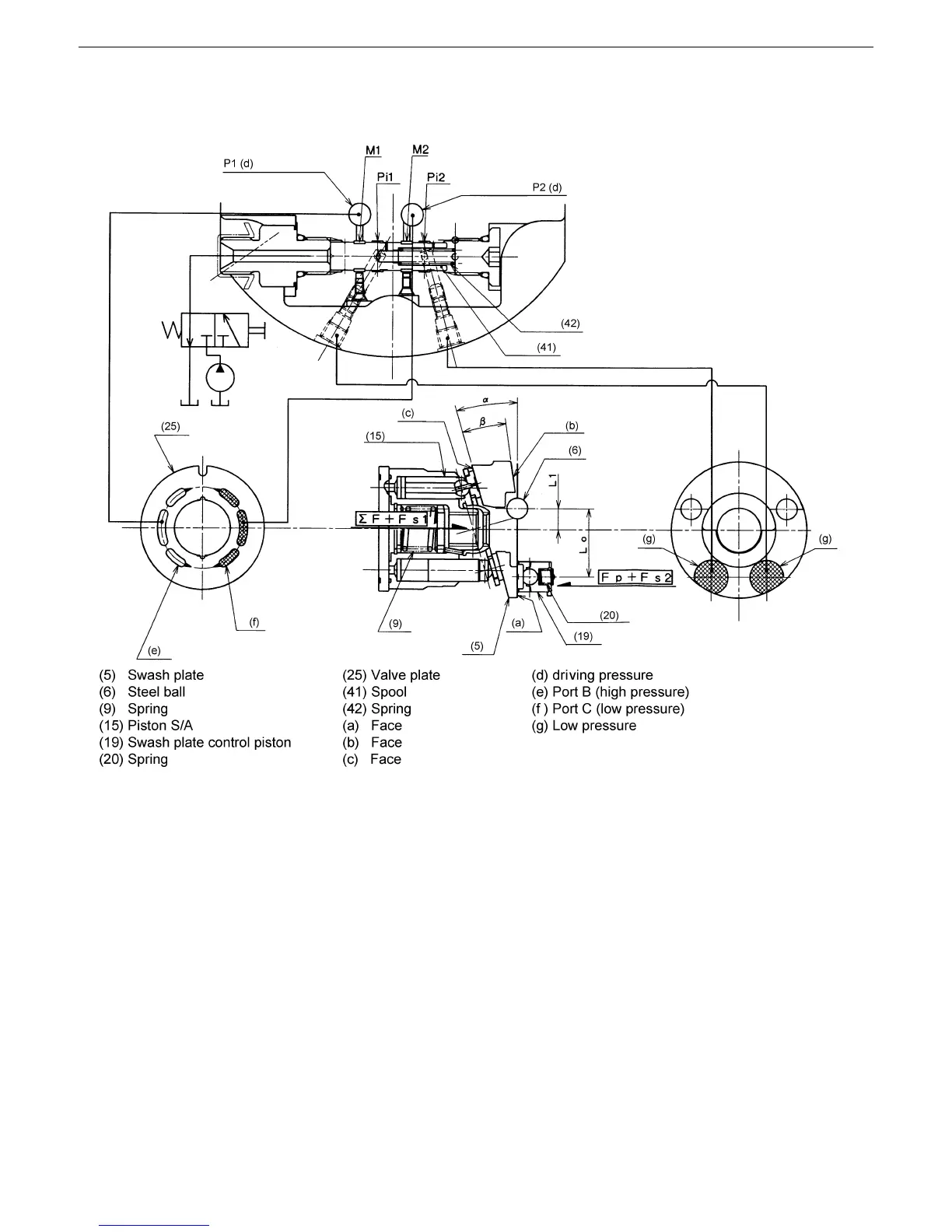
d. Function of Hi-Lo change
• 1st (low) speed
As shown in the figure, the swash plate (5) having three faces (a) to (c) is fitted to the flange holder
through the two steel balls (6) so that it can be tilted.
When the control valve is in the 1st speed position, the spring (42) positions the spool (41) as shown in
the figure to the left and the swash plate control piston (19) is connected to the port T via the ports Pi1 and
Pi2. Therefore no force for pushing the swash plate (5) is applied to the swash plate control piston (19).
The moment acting on the swash plate with the steel balls (6) serving as the tilting center is expressed as
shown bellow: where ƒ°F is the sum of the thrusts of the piston S/As (15) and Fs1 and Fs2 are the forces
of the spring (9).
The swash plate is stabilized on the face (a) and the swash plate angle becomes α, providing the
revolutions for the 1st (low) speed of the motor.
Fp = (Ap · P) = 0
Fp : Thrust of swash plate control piston
Ap : Pressure-applied area of swash plate control piston
P : Pressure
(ΣF + F s1) · L1 > (Fp + F s2) · Lo
 Loading...


