U20-3, U25-3 WSM Electrical system (Mechanism section)
V-M-15
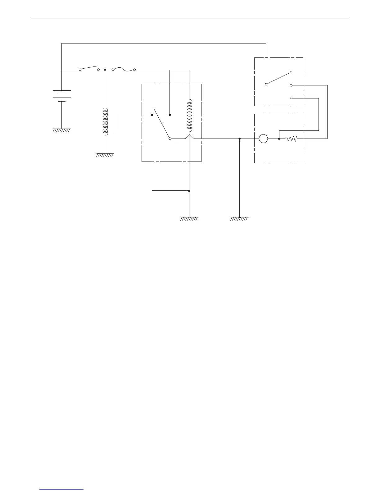
i. Heater circuit
(1) Current flow
1.Turn the key switch to the ON position, and the battery current starts flowing to the heater relay,
making the relay contact.
2.By changing the heater switch to the High and Low position, the heater can be controlled in two
steps.
(2) Electromagnetic braking
Turn the key switch to the OFF position with the heater switch still on, and the heater motor usually
keeps turning by inertial force and generates electricity. Since the relay terminal is always grounded,
however, the self-generated current causes an inverse electromagnetic action, which interrupts the
motor quickly. This process is called electromagnetic braking.
(3) Purpose of relay
Without the relay, the above-mentioned self-generated current at a stop of the heater motor might flow
into other solenoid valves for example. The relay is thus used to prevent malfunction of other devices.
1
Key SW
Engine
Stop
Solenoid
Heater relay
Heater
Lo
Hi
Heater SW
B
M
3
2
3b
 Loading...


