U20-3, U25-3 WSM Electrical system (Mechanism section)
V-M-14
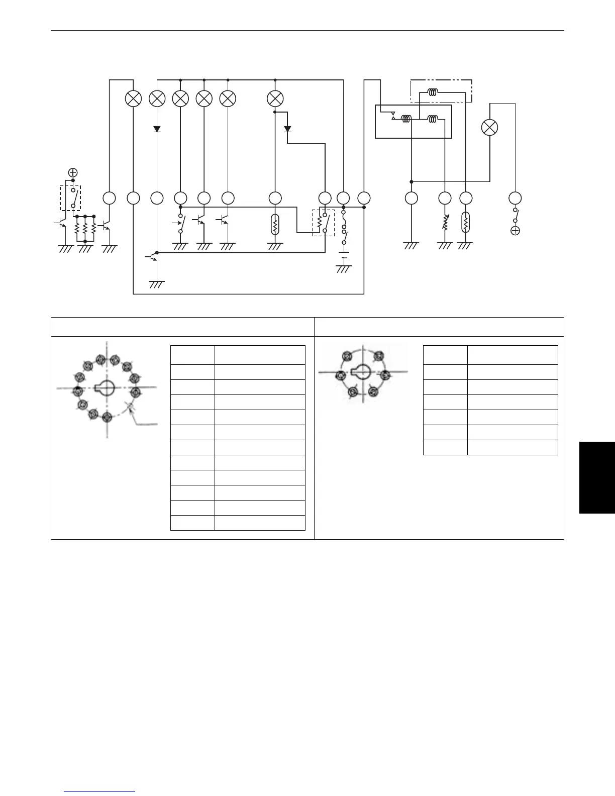
h. Meter panel
1. Turn the key switch to the ON position, and the battery current starts flowing as shown in the figure.
Because the engine oil pressure switch is of NC type, the check relay comes on too and all the warn-
ing lamps light up.(The regulator terminal L also lights up when the key switch is turned to the ON
position.)
2. When the engine has started and reached the specified speed, the engine oil pressure rises too and
the switch is turned off. The charge voltage also rises, which discontinues the current flow to the termi-
nal L. Thus the check relay turns itself off and all the warning lamps go out.
3. During usual operation, the indicator lamps are ready to light up according to their respective circuits.
Let's take some examples. The glow lamp stays on while the current is flowing to the glow plug. The
AI lamp is kept on during the AI function. The charge lamp lights up if the charge voltage drops below
the specified level. The fuel level lamp lights up if the fuel runs short.
12p connector 6p connector
1.4W
1.4W
1.4W
1.4W
1.4W
1.4W
3W
10 4 11 3 5 2 6 1
941 3 82
TEMP
FUEL
Glow plugs
Glow(+)
Charge
Oil pressure
Fuel level
Check relay
Lamp
Glow(-)
Regulator
L-terminal
()
Circuit diagram
GND
F.U.
T.U.
IG(+)
IG(+)
Lamp check
Auto glow unit
AI
System
No Connection
1 Engine Pressure
2IG(+)
3-
4Charge
5-
6-
7-
8Check SW
9Glow (+)
10 Glow(-)
11 Fuel level
(7)
(6)
(5)
(4)
(3)
(2)
(1)
Empty
(11)
(10)
(9)
(8)
No Connection
1 Lamp(+)
2 Fuel unit
3IG(+)
4System lamp
5GND
6 Temp. unit
(4)
(5)
(6)
(1)
(2)
(3)
 Loading...


