4-17
Cutting out Data with Register Marks
4
Extended Functions – Cutting –
When Cutting Failed
Checking the Sensor for the Register Mark Detection
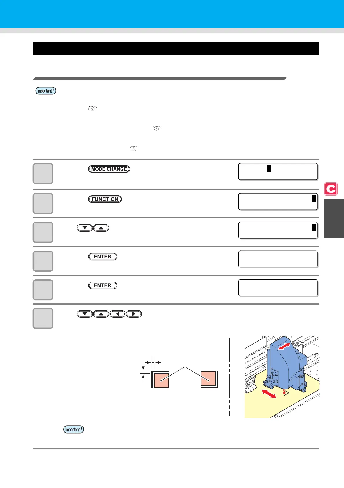
1
Press the key in LOCAL to select cutting
mode.
2
Press the key.
3
Press to select [MAINTENANCE].
4
Press the key twice.
5
Press the key.
• Light pointer will be lit.
6
Press to move the light pointer to the register mark detection
position.
• The register mark detection position should be at least 1 mm away from a register mark.
• You cannot check the response correctly by moving the head or medium manually. Be sure to
follow the steps below to check the response.
• For conditions of an already printed register mark, refer to "Notes on Inputting Data with Register
Marks" ( P.4-6).
• The setting values are kept in memory even when the power is turned OFF.
• The settings performed here for type and length of the register mark are reflected in the settings of
"Setting Register Mark Detection" ( P.4-11).
• The detection speed selected here will be used in the register mark detection operations thereafter.
• The pointer offset value and sensor gain setting value selected by this operation are not initialized by
"Initializing the Settings" ( P.4-37).
• The origin set here is registered as the origin for normal printing/cutting. If changing the
origin after completion of confirming the register mark sensor, perform the operation in
P.2-33 "When Changing the Origin".
<LOCAL .
C
> [ #01 ]
CUT 1 ( 3 0 / 6 0 / 0 . 3 0 )
FUNCT I ON
C
SETUP <ENT>
FUNCT I ON
C
MA I N T ENANCE < EN T >
MARK S ENSOR
SENSOR CHECK <e n t >
MARK S ENSOR
SIZE = 10mm
1 mm or more
away
Mark detection
position
Register mark:
Type 1
Register mark:
Type 2
 Loading...


