EasyManua.ls Logo

NAiS FP1 User Manual

Default Icon
280 pages
To Next Page IconTo Next Page
To Previous Page IconTo Previous Page
Page #111 background imageLoading...
Page #111 background image
5-3. Description of Basic Instructions
103
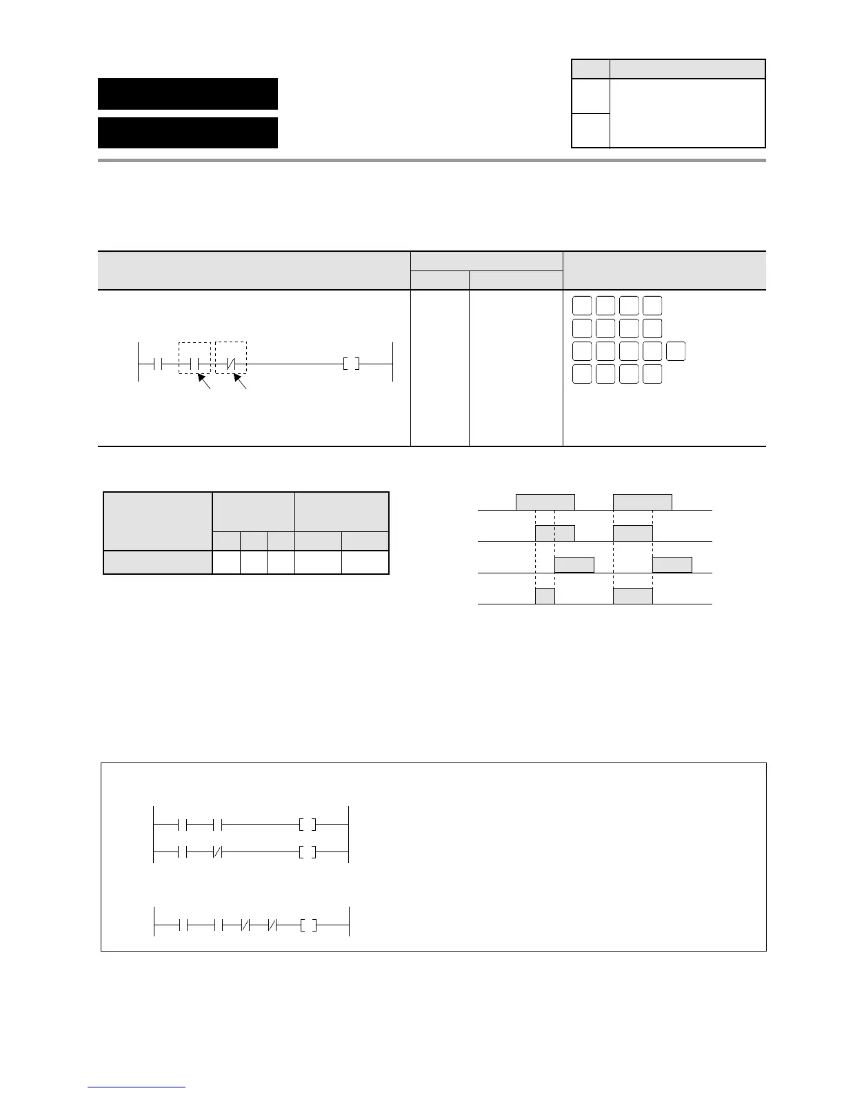
Outline AN: Connects a Form A (normally open) contact serially.
AN/: Connects a Form B (normally closed) contact serially.
Program example
Operands Time chart
Explanation of example
Y0 goes ON when both X0 and X1 turn ON and also X2 turns OFF.
Description
• Performs a logical AND operation with the results of the immediately preceding serially
connected operation.
Notes:
Use the AN instruction when the normally open contact (Form A contact) is serially connected. Use the
AN/ instruction when the normally closed contact (Form B contact) is serially connected.
The AN and AN/ instructions can be used consecutively.
ON
OFF
X0
ON
OFF
X1
ON
OFF
X2
ON
OFF
Y0
Timer/Counter
Contact
C
Relay
TRYX
Instruction
AN, AN/
AAA A A
A:
N/A: Not Available
Available
AN
AND
AN/
AND Not
Availability
Step
1
1
All series
Ladder Diagram FP Programmer II key operations
Boolean Non-ladder
Address Instruction
0
X1 Y0
AND
AND Not
X2
X0
ST
X-WX
ST
X-WX
ST
X-WX
0 WRT
AN
Y-WY
WRT1
AN
Y-WY
NOT
DT/Ld
WRT
OT
L-WL
AN
Y-WY
0 WRT
ST
X-WX
WRT2
0
1
2
3
ST X 0
AN X 1
AN/ X 2
OT Y 0
X2 X3
X0
Y0
Y1
X1
X0
Y0
X1 X2 X3

Table of Contents

Questions and Answers:

NAiS FP1 Specifications

General IconGeneral
BrandNAiS
ModelFP1
CategoryController
LanguageEnglish

Summary

Chapter 1: Features

1-1. Features

Details about the capabilities and functions of the FP1 controller, including advanced control and communication.

Chapter 2: Specifications

2-2. Specifications

Provides detailed technical data and performance characteristics of FP1 units, covering environmental and electrical specs.

Chapter 3: Installation and Wiring

3-1. Installation

Guides on how to physically mount FP1 units and related hardware using panel or DIN rail methods.

3-2. Expansion

Details on connecting expansion units and cables to the FP1 system, including proper alignment.

3-3. Wiring

Instructions and examples for electrical wiring of FP1 units, power supply, and I/O terminals.

Chapter 4: Before Programming

4-3. Programming with NPST-GR Software

Guides on using NPST-GR software for program entry, editing, monitoring, and data transfer.

Chapter 5: Basic Instructions

5-3. Description of Basic Instructions

Detailed explanations of individual basic instructions, including programming examples and time charts.

Chapter 6: High-level Instructions

6-3. Description of High-level Instructions

Detailed explanations of individual high-level instructions, including programming examples and flag conditions.

Chapter 7: Troubleshooting

7-1. Self-diagnostic Function

Explains the FP1's self-diagnostic features, including error types and operation monitor LEDs.

7-2. Troubleshooting

Provides troubleshooting steps based on error LEDs, common errors, and system status.

Related product manuals