EasyManua.ls Logo

NAiS FP1 User Manual

Default Icon
280 pages
To Next Page IconTo Next Page
To Previous Page IconTo Previous Page
Page #123 background imageLoading...
Page #123 background image
Outline TMR: Sets the ON-delay timer for 0.01 s units (0 to 327.67 s)
TMX: Sets the ON-delay timer for 0.1 s units (0 to 3276.7 s)
TMY: Sets the ON-delay timer for 1 s units (0 to 32767 s)
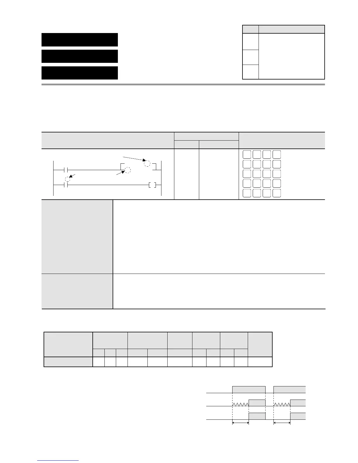
Program example
Operands
Explanation of example Time chart
ON
OFF
X0
ON
OFF
T5
ON
OFF
Y0
3s 3s
• Three seconds after X0 turns ON, timer contact T5
turns ON. Then Y0 goes ON.
Timer/Counter
area
EV
Relay
SVWRWYWX
Instruction
Set value
N/A N/A N/A A N/A
A:
N/A: Not Available
Register
DT
N/A
IYIX
N/A N/A
HK
A N/A
Constant
Index
modifier
N/A
Index
register
Available
5-3. Description of Basic Instructions
TMR
0.01s units timer
TMX
0.1s units timer
TMY
1s units timer
Ladder Diagram FP Programmer II key operations
Boolean Non-ladder
Address Instruction
0
X0
T5
Set value
Timer instruction
number
5
Y0
TM X 30
4
ST
X-WX
TM
T-SV
ENT5
ST
X-WX
ST
X-WX
0 WRT
OT
L-WL
AN
Y-WY
0 WRT
(BIN)
K/H
0 WRT
TM
T-SV
ST
X-WX
WRT5 WRT
3
0
1
4
5
ST X 0
TM X 5
K30
ST T 5
OT Y 0
Availability
Step
3
3
4
All series
Timer instruction number C14 and C16 series: up to 128
C24, C40, C56, and C72 series: up to 144
The number of the TM instructions is shared with that of the CT instructions.
You can change the sharing of TM and CT instructions through the system
registers.
The default value of the TM and CT instruction is,
for C14 and C16 series:
TM instruction: 0 to 99, CT instruction: 100 to 127
for C24, C40, C56, and C72 series:
TM instruction: 0 to 99, CT instruction: 100 to 143
Set value Range: K0 to K32767
Decimal constant or timer set value area (SVn)* whose number is same as its
timer instruction number (n)
*SVn” can be specified only when the version of the CPU is 2.7 or later.
115

Table of Contents

Questions and Answers:

NAiS FP1 Specifications

General IconGeneral
BrandNAiS
ModelFP1
CategoryController
LanguageEnglish

Summary

Chapter 1: Features

1-1. Features

Details about the capabilities and functions of the FP1 controller, including advanced control and communication.

Chapter 2: Specifications

2-2. Specifications

Provides detailed technical data and performance characteristics of FP1 units, covering environmental and electrical specs.

Chapter 3: Installation and Wiring

3-1. Installation

Guides on how to physically mount FP1 units and related hardware using panel or DIN rail methods.

3-2. Expansion

Details on connecting expansion units and cables to the FP1 system, including proper alignment.

3-3. Wiring

Instructions and examples for electrical wiring of FP1 units, power supply, and I/O terminals.

Chapter 4: Before Programming

4-3. Programming with NPST-GR Software

Guides on using NPST-GR software for program entry, editing, monitoring, and data transfer.

Chapter 5: Basic Instructions

5-3. Description of Basic Instructions

Detailed explanations of individual basic instructions, including programming examples and time charts.

Chapter 6: High-level Instructions

6-3. Description of High-level Instructions

Detailed explanations of individual high-level instructions, including programming examples and flag conditions.

Chapter 7: Troubleshooting

7-1. Self-diagnostic Function

Explains the FP1's self-diagnostic features, including error types and operation monitor LEDs.

7-2. Troubleshooting

Provides troubleshooting steps based on error LEDs, common errors, and system status.

Related product manuals