146
6-1. Configuration of High-level Instructions
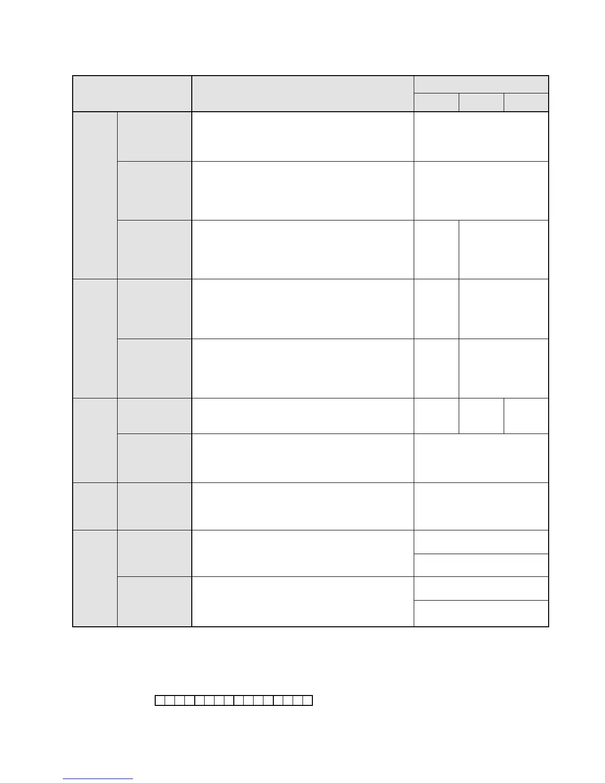
3. Operands for High-level Instructions
■ Registers and Constants
• The word relays (WX, WY, WR), timer/counter area (SV, EV), register (DT), index registers (IX, IY) and constants
(K, H) consist of 1 word (16 bits) and are handled as word units.
• The word addresses are expressed in decimals.
Word external
input relay
(WX)
Word external
output relay
(WY)
Word internal
relay (WR)
Timer/Counter
set value area
(SV)
Timer/Counter
elapsed value
area (EV)
Data register
(DT)
Special data
register (DT)
Index register
(IX, IY)
Decimal
constant (K)
Hexadecimal
constant (H)
WX0 to WX12
(= X0 to X12F)
WY0 to WY12
(= Y0 to Y12F)
DT9000 to DT9069
IX, IY
C14/C16
Relay
Timer/
Counter
area
WR0
to
WR15
(= R0 to
R15F)
Item Function
Numbering
“WX” expresses an external input relay “X”.
“WX” handles the external input relays “X” in units
of words (1 word = 16 bits).
Therefore, “WX0” means 16 bits from “X0” to “XF”.
“WY” expresses an external output relay “Y”.
“WY” handles the external output relays “Y” in
units of words (1 word = 16 bits).
Therefore, “WY1” means 16 bits from “Y10” to
“Y1F”.
“WR” expresses an internal relay “R”.
“WR” handles the internal relays in units of
words (1 word = 16 bits).
Therefore, “WR2” means 16 bits from
“R20” to “R2F”.
“SV” is a memory area where the preset (set)
value of the TM/CT instructions is stored.
Each “SV” consists of 16 bits.
The address of this memory area corresponds
to the TM/CT instruction number.
“EV” is a memory area where the count (elapsed)
value of the TM/CT instructions is stored.
Each “EV” consists of 16 bits.
The address of this memory area corresponds
to the TM/CT instruction number.
“DT” is a memory area for data processed
within the programmable controllers and each
“DT” consists of 16 bits.
The special data register is a memory area that
has special applications. Refer to page 226,
“8-4. Table of Special Data Registers” for details
about the special data register.
The index register can be used as an address
modifier for WX, WY, WR, SV, EV, DT, K and H.
Refer to page 193, “2. How to Use Index Registers
(IX, IY)”.
Decimal constants
Hexadecimal constants
Register
Constant
Index
register
C24/C40 C56/C72
WR0 to WR62
(= R0 to R62F)
SV0
to
SV127
SV0 to SV143
DT0
to
DT255
DT0
to
DT1659
DT0
to
DT6143
16-bit constant (word):
K-32768 to K32767
32-bit constant (double word):
K-2147483648 to K2147483647
16-bit constant (word):
H0 to HFFFF
32-bit constant (double word):
H0 to HFFFFFFFF
EV0
to
EV127
EV0 to EV143
 Loading...
