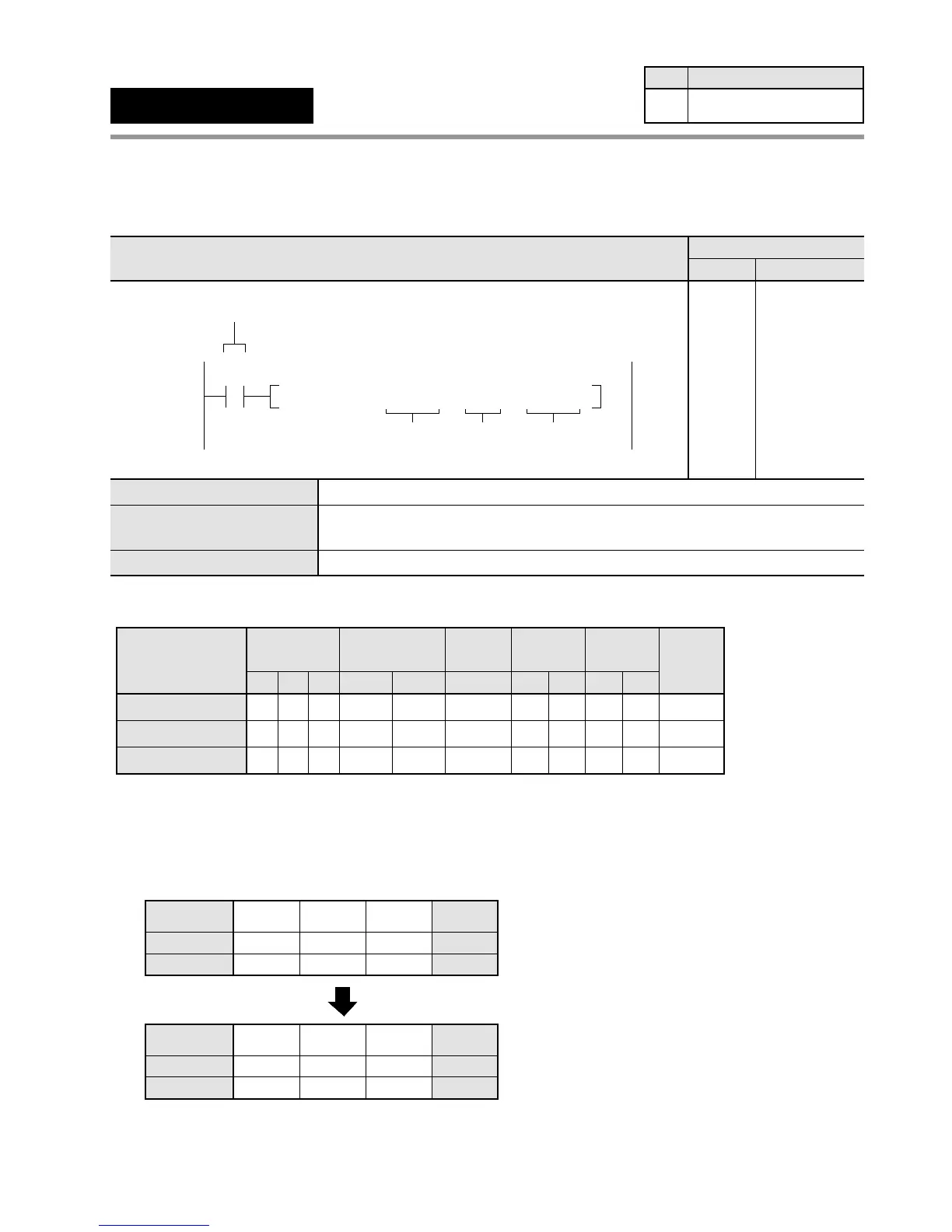
6-3. Description of High-level Instructions
Outline Copies the hexadecimal digits in one 16-bit area to the specified digit in
another 16-bit area.
Program example
■ Operands
■ Explanation of example
• The hexadecimal digit 0 of the data register DT100 is copied to hexadecimal digit 0 of word external output relay
WY0 when trigger X0 turns ON.
n: H0
Bit position
DT100
0000
0001
11 8
0100
1001
30
Source [S]: H149
X0: ON
15 ••12 •• ••
74
••
Hexadecimal
digit position
3210
Bit position
WY0
0000
1000
11 8
1010
1001
30
Destination [D]: H8A9
15 ••12 •• ••
74
••
Hexadecimal
digit position
3210
In this case, only the lower 4 bits of WY0 change value.
"
"
"
"
"
Timer/Counter
EV
Relay
SVWRWYWX
Operand
S
AAA A
A:
N/A: Not Available
Register
DT
A
IYIX
AA
HK
AA
Constant
Index
modifier
A
Index
register
Available
A
n
AAA A A A A A A AA
N/A A A A A A A N/A N/A AA
D
F6
(DGT)
Hexadecimal digit move
Availability
Step
7 All series
S
n
D
16-bit equivalent constant or 16-bit area (source)
16-bit equivalent constant or 16-bit area (specifies source and destination
hexadecimal digit position and number of hexadecimal digits)
16-bit area (destination)
Ladder Diagram
Boolean Non-ladder
Address Instruction
10
X0
F6 DGT , DT100 , H0 , WY0
S
D
Trigger
n
10
11
ST X 0
F 6 (DGT)
DT 100
H0
WY 0
162
 Loading...
