47
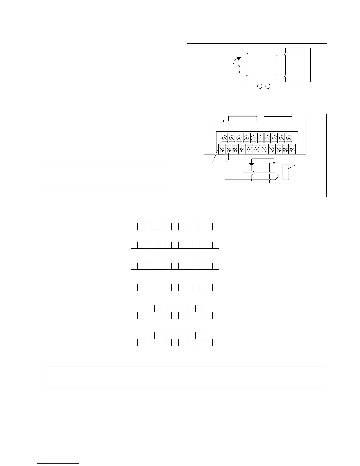
■ Wiring the LED-equipped Reed Switch
■ Connecting an input device with a different voltage (ex.: a 5 V sensor, etc.)
Note:
4) Input Terminal Layouts
Notes:
• Do not connect input devices to the input terminals indicated with a “•” symbol.
• The + common input type is also available for C16, C24 and E24 series.
• C14 series:
AC type
• C16 series:
AC type
DC type
• C24, E24 series:
AC type
DC type
1357 9BDF
246 AC0
•
8E
COM
(±)
DC type
•
1357 9BDF
246 AC0
•
8E
•
COM
(±)
COM
(±)
0123
24V
(+)
COM
(±)
4567
24V
(–)
0123
COM
(±)
4567
••
0123
24V
(+)
COM
(±)
4567
24V
(–)
0123
COM
(±)
4567
••
24V
(–)
24V
(+)
COM
(±)
• Some sensors do not allow for this type of
use, therefore check the specifications of the
sensor before wiring.
• When connecting a device with a power supply
voltage different from the FP1 input voltage, such
as a 5 V sensor, connect in common to the - side
of the built-in DC power output terminal as shown
in the diagram.
COM
LED-equipped
reed switch
FP1
Input
terminal
–
+
10 V DC
or more
FP1-036-93-B
• When a LED is connected in serial to an input
contact such as the LED-equipped reed switch,
make the voltage applied to the FP1 input circuit
greater than 10 V. In particular, take care when
connecting a number of switches in serial.
3-3. Wiring
0246
1357
24 V DC COM
-
+
(
±
)
8ACE
9BDF
COM
(
±
)
FP1-037-93-B
Sensor (5 V DC type)
Internal
circuit
Output
+V
0V
Built-in DC
power output
terminal (-)
5 V
DC
 Loading...
