EasyManua.ls Logo

NAiS FP1 User Manual

Default Icon
280 pages
To Next Page IconTo Next Page
To Previous Page IconTo Previous Page
Page #189 background imageLoading...
Page #189 background image
181
Outline Compares one 16-bit data with another.
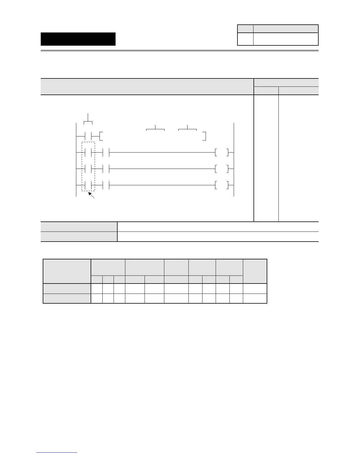
Program example
Operands
Explanation of example
• Compares decimal constant K100 with the contents of data register DT0 when trigger X0 turns ON.
The compared result is stored in special internal relays R900A, R900B, and R900C.
When DT0 > K100, R900A turns ON and internal relay R0 turns ON.
When DT0 = K100, R900B turns ON and internal relay R1 turns ON.
When DT0 < K100, R900C turns ON and internal relay R2 turns ON.
In this program example, the comparison will be performed only when X0 turns ON.
Timer/Counter
EV
Relay
SVWRWYWX
Operand
S1
AAA A
A:
N/A: Not Available
Register
DT
A
IYIX
AA
HK
AA
Constant
Index
modifier
A
Index
register
Available
A
S2
AAA A A A A A A AA
6-3. Description of High-level Instructions
S1
S2
16-bit equivalent constant or 16-bit area to be compared
Ladder Diagram
Boolean Non-ladder
Address Instruction
20
X0
F60 CMP , DT 0 , K100
S1 S2
Be sure to use the same trigger
as the trigger used to execute F60 (CMP).
X0 R0
R900A
26
X0 R1
R900B
30
X0 R2
R900C
34
Trigger
20
21
26
27
29
30
31
33
34
35
37
ST X 0
F 60 (CMP)
DT 0
K 100
ST X 0
AN R 900A
OT R 0
ST X 0
AN R 900B
OT R 1
ST X 0
AN R 900C
OT R 2
F60
(CMP)
16-bit data compare
Availability
Step
5
All series

Table of Contents

Questions and Answers:

NAiS FP1 Specifications

General IconGeneral
BrandNAiS
ModelFP1
CategoryController
LanguageEnglish

Summary

Chapter 1: Features

1-1. Features

Details about the capabilities and functions of the FP1 controller, including advanced control and communication.

Chapter 2: Specifications

2-2. Specifications

Provides detailed technical data and performance characteristics of FP1 units, covering environmental and electrical specs.

Chapter 3: Installation and Wiring

3-1. Installation

Guides on how to physically mount FP1 units and related hardware using panel or DIN rail methods.

3-2. Expansion

Details on connecting expansion units and cables to the FP1 system, including proper alignment.

3-3. Wiring

Instructions and examples for electrical wiring of FP1 units, power supply, and I/O terminals.

Chapter 4: Before Programming

4-3. Programming with NPST-GR Software

Guides on using NPST-GR software for program entry, editing, monitoring, and data transfer.

Chapter 5: Basic Instructions

5-3. Description of Basic Instructions

Detailed explanations of individual basic instructions, including programming examples and time charts.

Chapter 6: High-level Instructions

6-3. Description of High-level Instructions

Detailed explanations of individual high-level instructions, including programming examples and flag conditions.

Chapter 7: Troubleshooting

7-1. Self-diagnostic Function

Explains the FP1's self-diagnostic features, including error types and operation monitor LEDs.

7-2. Troubleshooting

Provides troubleshooting steps based on error LEDs, common errors, and system status.

Related product manuals