EasyManua.ls Logo

NAiS FP1 User Manual

Default Icon
280 pages
To Next Page IconTo Next Page
To Previous Page IconTo Previous Page
Page #119 background imageLoading...
Page #119 background image
111
5-3. Description of Basic Instructions
SET
Set
RST
Reset
Outline SET: Holds the contact (in bit) ON.
RST: Holds the contact (in bit) OFF.
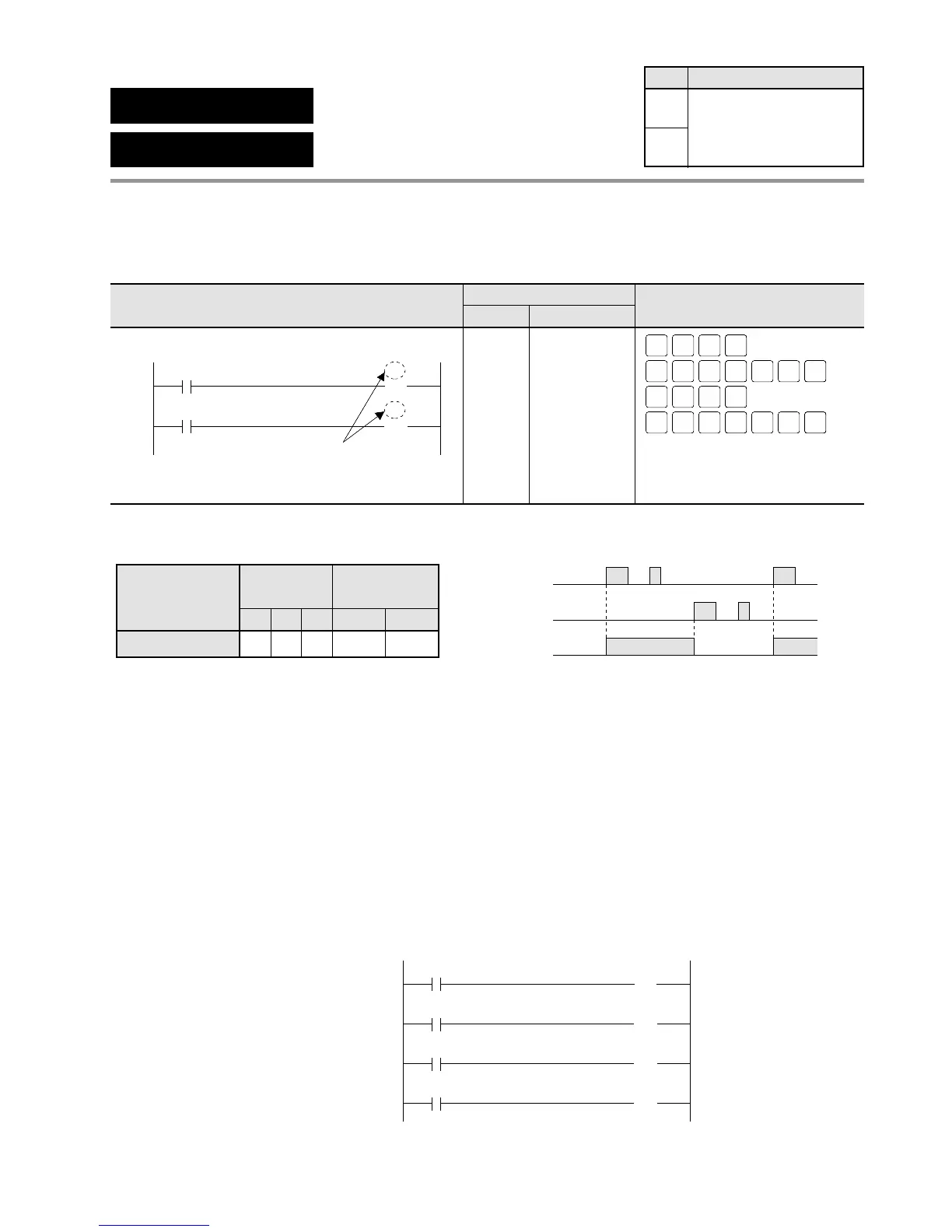
Program example
Operands Time chart
Explanation of example
When X0 turns ON, Y0 goes ON and holds the contact (in bit) ON.
When X1 turns ON, Y0 goes OFF and holds the contact (in bit) OFF.
Description
The SET instruction executes when the trigger is turned ON. Output turns ON and holds the
contact (in bit) ON regardless of the trigger’s state changes.
The RST instruction executes when trigger is turned ON. Output turns OFF and holds the
contact (in bit) OFF regardless of the trigger’s state changes.
You can use the same number for relays (Y and R) with the SET and RST instructions as
many times as you like.
X0 Y0
S 〉!
X1 Y0
R 〉!
X2 Y0
S 〉!
X3 Y0
R 〉!
ON
OFF
X0
ON
OFF
X1
ON
OFF
Y0
Timer/Counter
Contact
C
Relay
TRYX
Instruction
SET, RST
N/A A A N/A N/A
A:
N/A: Not Available
Available
Ladder Diagram FP Programmer II key operations
Boolean Non-ladder
Address Instruction
0
X0 Y0
4
X1 Y0
S 〉!
R 〉!
Output number
of relay
SHIFT
SC
1
ST
X-WX
ST
X-WX
WRT0 WRT
SHIFT
SC
WRTWRT9
AN
Y-WY
0
ST
X-WX
ST
X-WX
WRT1 WRT
SHIFT
SC
1
SHIFT
SC
WRTWRTA
AN
Y-WY
0
0
1
4
5
ST X 0
SET Y 0
ST X 1
RST Y 0
Availability
Step
3
3
All series

Table of Contents

Questions and Answers:

NAiS FP1 Specifications

General IconGeneral
BrandNAiS
ModelFP1
CategoryController
LanguageEnglish

Summary

Chapter 1: Features

1-1. Features

Details about the capabilities and functions of the FP1 controller, including advanced control and communication.

Chapter 2: Specifications

2-2. Specifications

Provides detailed technical data and performance characteristics of FP1 units, covering environmental and electrical specs.

Chapter 3: Installation and Wiring

3-1. Installation

Guides on how to physically mount FP1 units and related hardware using panel or DIN rail methods.

3-2. Expansion

Details on connecting expansion units and cables to the FP1 system, including proper alignment.

3-3. Wiring

Instructions and examples for electrical wiring of FP1 units, power supply, and I/O terminals.

Chapter 4: Before Programming

4-3. Programming with NPST-GR Software

Guides on using NPST-GR software for program entry, editing, monitoring, and data transfer.

Chapter 5: Basic Instructions

5-3. Description of Basic Instructions

Detailed explanations of individual basic instructions, including programming examples and time charts.

Chapter 6: High-level Instructions

6-3. Description of High-level Instructions

Detailed explanations of individual high-level instructions, including programming examples and flag conditions.

Chapter 7: Troubleshooting

7-1. Self-diagnostic Function

Explains the FP1's self-diagnostic features, including error types and operation monitor LEDs.

7-2. Troubleshooting

Provides troubleshooting steps based on error LEDs, common errors, and system status.

Related product manuals