2-1. Parts Terminology and Functions
I/O Terminals:
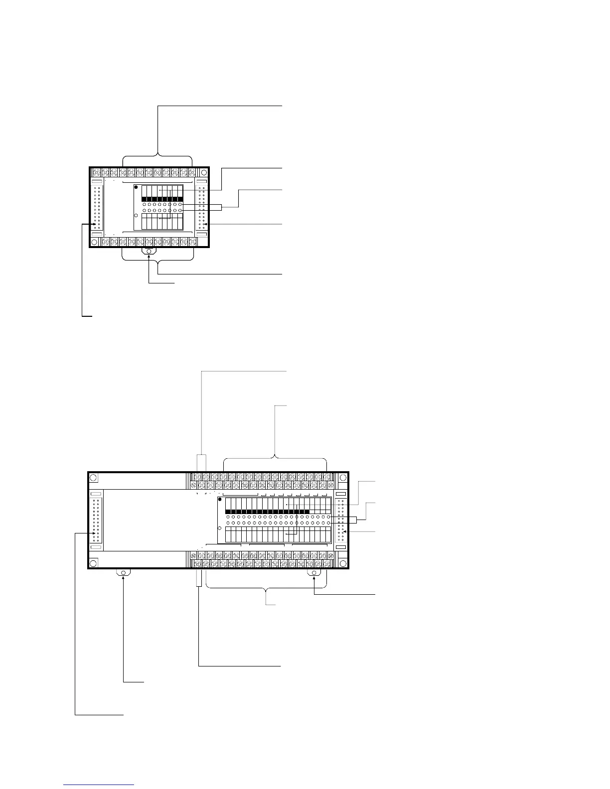
• Input only type and I/O type:
E8 series (Input 4 points)/E16 series (Input 8 points)
• Output only type:
E8 series (Output 4 points)/E16 series (Output 8 points)
I/O Name Board
I/O State Indicators:
Indicates the input and output ON/OFF states.
Expansion Connector (right side):
Connects to the FP1 Expansion Unit or FP1 Intelligent Unit (FP1 A/D
Converter Unit or FP1 D/A Converter Unit) or FP1 I/O Link Unit.
See page 12 and 42.
I/O Terminals:
• Input only type and I/O type:
E8 series (Input 4 points)/E16 series (Input 8 points)
• Output only type:
E8 series (Output 4 points)/E16 series (Output 8 points)
DIN Rail
Attachment Lever
Expansion Connector (left side):
Connects to the FP1 Control Unit or FP1 Expansion Unit.
See page 12 and 42.
Expansion Connector (left side):
Connects to the FP1 Control Unit or FP1 Expansion Unit. See page 12 and 42.
Power Supply Terminals:
• AC type Control Unit: power supply terminals for 100 V AC to 240 V AC
• DC type Control Unit: power supply terminals for 24 V DC
Output Terminals:
E24 series: 8 points, E40 series 16 points
This terminal block is removable with screws at both ends.
Terminals marked with “•” cannot be used as output terminals.
Input Terminals:
E24 series: 16 points, E40 series: 24 points
Input voltage range: 12 V DC to 24 V DC
This terminal block is removable with screws at both ends.
Terminals marked with “•” cannot be used as output terminals.
Built-in DC Power Output Terminals for Inputs
(AC type only):
DC power for inputs can be supplied from these terminals.
See page 45.
DIN Rail
Attachment Lever
I/O Name Board
I/O State Indicators:
Indicates the input and output ON/OFF states.
Expansion Connector (right side):
Connects to the FP1 Expansion Unit or FP1
Intelligent Unit (FP1 A/D Converter Unit or FP1
D/A Converter Unit) or FP1 I/O Link Unit.
See page 12 and 42.
DIN Rail Attachment Lever
 Loading...
