62
4-2. How to Program the Programmable Controller
4-2. How to Program the Programmable
Controller
1. Making a Ladder Diagram
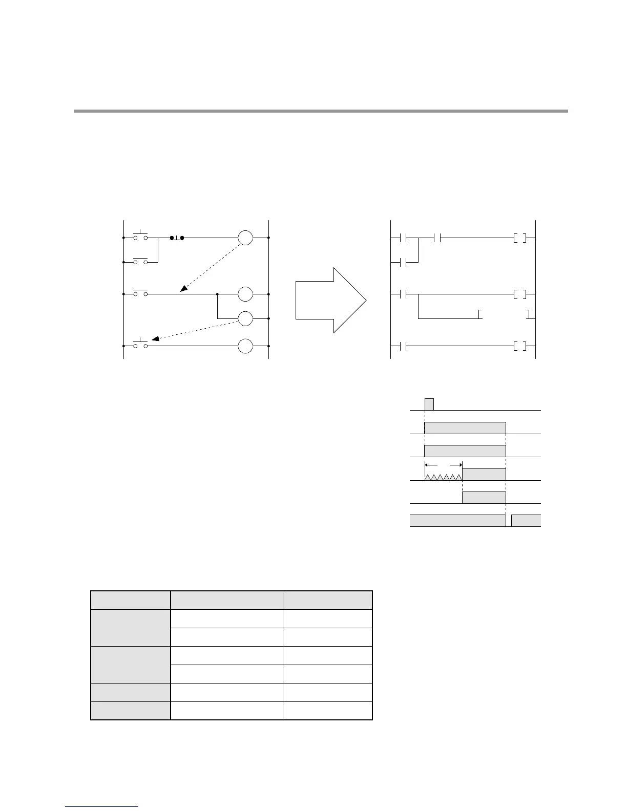
Originally, programmable controllers were designed as a replacement for relay-controlled systems. Therefore,
programs can be easily created with a relay sequence circuit as shown below.
■ Explanation of Movement ■ Time chart
■ I/O Allocation
The input and output addresses of the programmable controller are allocated according to the condition in the
sequence diagram.
• All relays and timers used in the sequence circuit are replaced with internal relays and timers in the programmable
controller.
1) When push-button switch A is pressed, the coil of
relay R0 is energized and its contacts turn ON.
2) Since contact 1 of relay R0 supplies power to the
coil of relay R0, the coil stays energized even if
switch A is turned OFF (self-hold circuit).
3) Contact 2 of relay R0 supplies power to lamp Y0
and timer T0. The lamp turns ON and the timer starts
timing operation.
4) After the preset time (e.g., 3 s), timer contact T0 turns
ON and motor Y1 starts operation.
5) When push-button switch B is pressed, the coil of
relay R0 is de-energized and all the power turns OFF.
 Loading...
