46
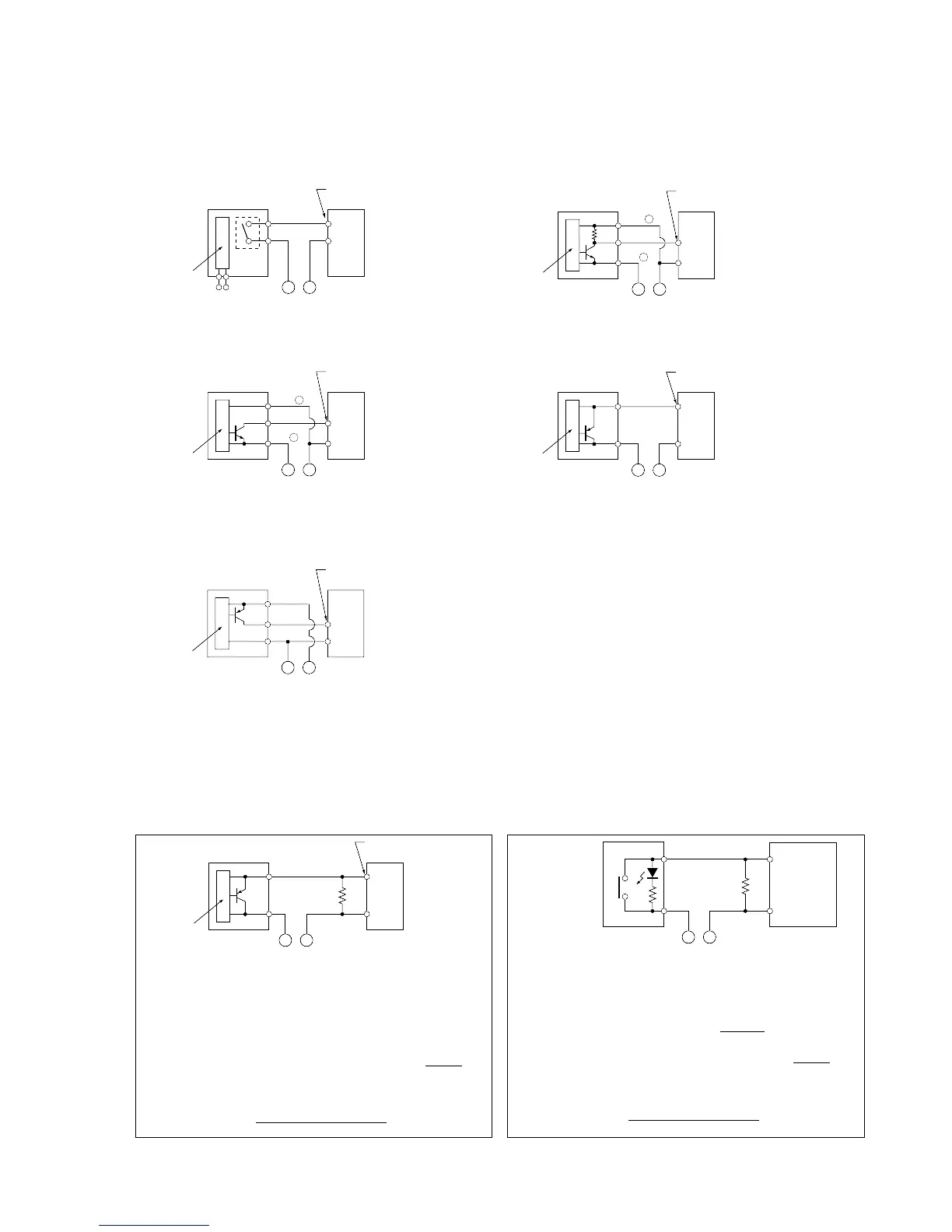
3) Input Wiring Examples
■ Wiring the Photoelectric Sensors
Due to the difference in the photoelectric sensor’s output scheme, connect as shown below:
• Relay output type • Universal output type
• NPN open collector output type • Two-wire type
• PNP open collector output type
(Control Units and Expansion Units with common +/– inputs)
COM
LED-equipped
limit switch
FP1
Input
terminal
–
+
Bleeder
resistor
FP1-035-93-B
Rr
COM
Sensor
Internal
circuit
FP1
Input terminal
–
+
Bleeder
resistor
FP1-034-93-B
R
■ Wiring the LED-equipped Limit Switch
• If the input of the FP1 is not turned OFF or if the
LED of the limit switch is kept ON because of
the leakage current, the use of a bleeder resistor
is recommended, as shown below.
■ Wiring the Two-wire Type Sensor
• If the input of the FP1 is not turned OFF because of
leakage current from the sensor, the use of a bleeder
resistor is recommended, as shown below.
COM
Sensor
Internal
circuit
FP1
Input terminal
–
Power supply
for input
FP1-033-93-B
+
COM
Sensor
Internal
circuit
FP1
Input terminal
–
+
Power supply
for input
FP1-032-93-B
COM
Sensor
Internal
circuit
FP1
Input terminal
–
+
Power supply
for input
FP1-030-93-B
Vcc
0V
+
–
COM
Sensor
Internal
circuit
FP1
Input terminal
–
+
Power supply
for input
FP1-031-93-B
Vcc
0V
+
–
COMSensor
Internal
circuit
FP1
Input terminal
–
+
Power supply
for input
FP1-029-93-B
Sensor
power supply
3-3. Wiring
I: Sensor’s leakage current (mA)
The OFF voltage of the FP1 input is 2.5 V, therefore,
select an R value so that the voltage between the COM
terminal and the input terminal will be less than 2.5 V.
(The impedance of the FP1 input terminal is 3 kΩ.)
The resistance R of the bleeder resistor is : R
7.5
3
I-2.5
The wattage W of the resistor is:
W=
(Power supply voltage)
2
× (3~5)
R
r: Internal resistor of limit switch (kΩ)
R: Bleeder resistance (kΩ)
The OFF voltage of the FP1 input is 2.5 V, therefore
when the power supply voltage is 24 V, select R so that
the current will be greater than I =
24 - 2.5
r
The resistance R of the bleeder resistor is: R
7.5
3
I-2.5
The wattage W of the resistor is:
W=
(Power supply voltage)
2
× (3~5)
R
 Loading...
