17
1-4. Programming Tools
Notes:
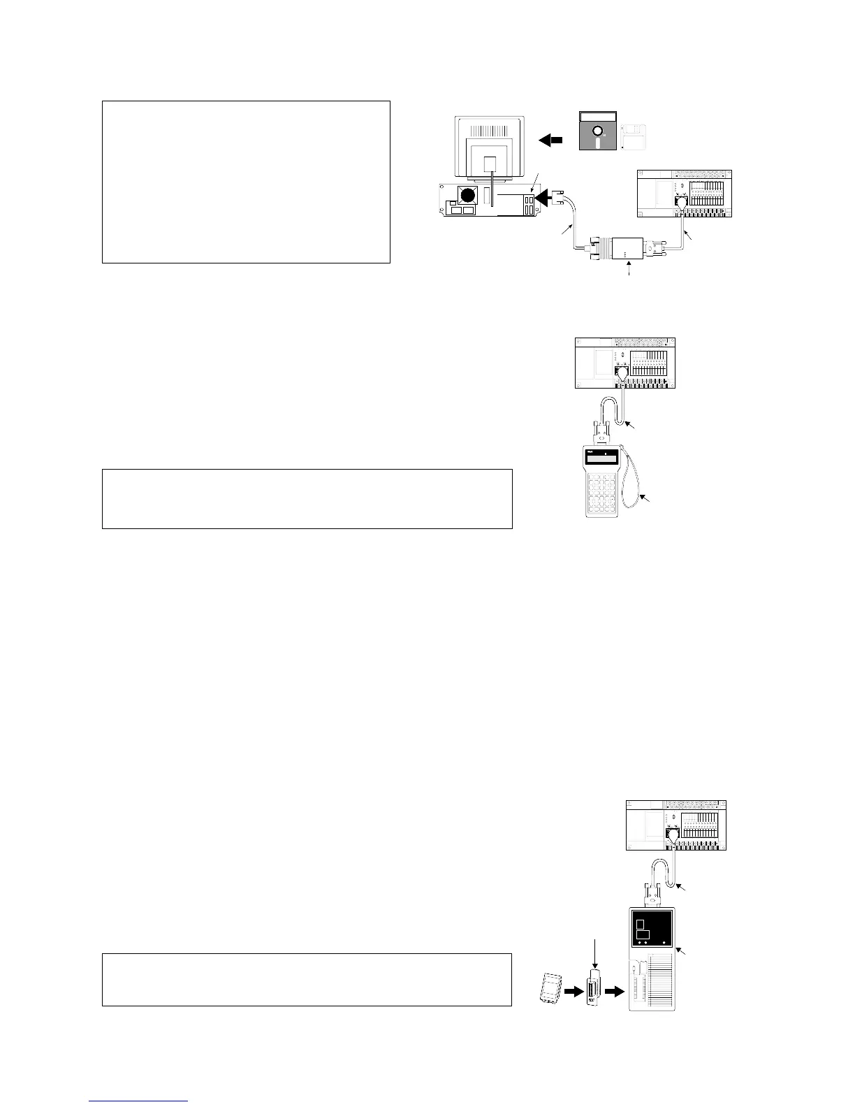
2) FP Programmer II
With the hand-held FP Programmer II, such operations as writing, reading,
and retrieval of programs can be performed.
Necessary tools
• FP1 Peripheral Cable:
0.5 m / 1.640 ft.: AFP15205
3 m / 9.843 ft.: AFP1523
• FP Programmer II: AFP1114
Note:
2. How to Program ROM
• Using an FP ROM Writer or a commercially available ROM programmer, the contents of the FP1’s internal RAM
can be written to ROM (memory).
• The following types of ROM (memory) are available:
- Memory (EPROM): AFP1201
Memory for storing programs. Writing is done with an FP ROM Writer or a commercially available ROM
writer.
- Master Memory (EEPROM): AFP1202 (for C24 and C40 series), AFP1203 (for C56 and C72 series)
Memory for copying programs. Writing is done with a master memory attached to the FP1 Control Unit.
■ Writing a program to the memory (EPROM) with an FP ROM Writer
[FP1’s internal RAM Memory]
The content of the FP1’s internal RAM is written directly to the
memory (EPROM).
Necessary tools
• FP1 Peripheral Cable:
0.5 m / 1.640 ft.: AFP15205
3 m / 9.843 ft.: AFP1523
• FP ROM Writer: AFP5651
• Socket adapter for FP ROM Writer:AFP1810
• Memory (EPROM): AFP1201
Note:
• Refer to page 86, “4-5. Memory Unit Creation and ROM
Operation” and “FP ROM WRITER Technical Manual”, for
details about programming ROM.
• Refer to page 86, “4-5. Memory Unit Creation and ROM
Operation” and “FP PROGRAMMER II Operation Manual”, for
details about writing programs using the FP Programmer II.
• Refer to page 86, “4-5. Memory Unit
Creation and ROM Operation” and “NPST-
GR Manual”, for details about writing
programs using the NPST-GR Software.
• Refer to page 260, “8-10. Product Types”,
for details about RS232C cable wiring.
• When using NPST-GR Software Ver. 2,
refer to page 241, “1. Differences Between
NPST-GR Ver. 2.4 and Ver. 3.1.”
F.G.
PROG.
max.
min.
PROG.
ERR.
max.
min.
F.G.
PROG.
max.
min.
PROG.
ERR.
max.
min.
MATUSITA ELECTRIC WORKS. LTD
F.G.
PROG.
max.
min.
PROG.
ERR.
max.
min.
.