EasyManua.ls Logo

NAiS FP1 User Manual

Default Icon
280 pages
To Next Page IconTo Next Page
To Previous Page IconTo Previous Page
Page #197 background imageLoading...
Page #197 background image
189
Outline Converts BCD code that expresses 4-digit decimals to 16-bit binary data.
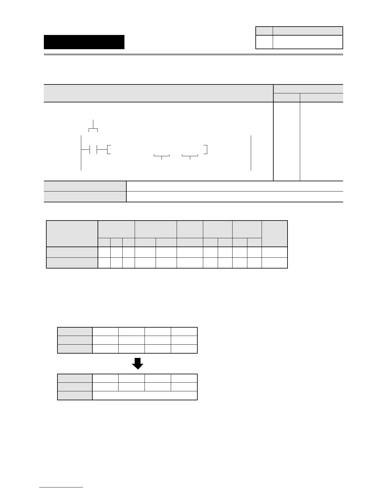
Program example
Operands
* The K constant available here is in the range of K0 to K9999.
** The H data specified here should be in the form of BCD code that express 4-digit decimal ranging from H0 (BCD) to H9999 (BCD).
Explanation of example
• Converts word external input relay WX0 to 16-bit binary data when trigger X0 turns ON.
The converted data is stored in data register DT0.
Bit position
DT0
Decimal
0000
0000
11 8
0000
1111
30
15 ••12 •• ••
74
••
K15
X0: ON
Source [S]: H15 (BCD)
Destination [D]: K15
Bit position
WX0
BCD H code
0000
0000
11 8
0001
0101
30
15 ••12 •• ••
74
••
0015
Timer/Counter
EV
Relay
SVWRWYWX
Operand
S
AAA A
A:
N/A: Not Available
Register
DT
A
IYIX
AA
HK
A* A**
Constant
Index
modifier
A
Index
register
Available
A
D
N/A A A A A A A N/A N/A AA
6-3. Description of High-level Instructions
F81
(BIN)
4-digit BCD data 16-bit data
Availability
Step
5 All series
S
D
4-digit BCD equivalent constant or 16-bit area for 4-digit BCD data (source)
16-bit area for storing 16-bit binary data (destination)
Ladder Diagram
Boolean Non-ladder
Address Instruction
10
X0
F81 BIN , WX0 , DT 0
D
Trigger
S
10
11
ST X 0
F 81 (BIN)
WX 0
DT 0

Table of Contents

Questions and Answers:

NAiS FP1 Specifications

General IconGeneral
BrandNAiS
ModelFP1
CategoryController
LanguageEnglish

Summary

Chapter 1: Features

1-1. Features

Details about the capabilities and functions of the FP1 controller, including advanced control and communication.

Chapter 2: Specifications

2-2. Specifications

Provides detailed technical data and performance characteristics of FP1 units, covering environmental and electrical specs.

Chapter 3: Installation and Wiring

3-1. Installation

Guides on how to physically mount FP1 units and related hardware using panel or DIN rail methods.

3-2. Expansion

Details on connecting expansion units and cables to the FP1 system, including proper alignment.

3-3. Wiring

Instructions and examples for electrical wiring of FP1 units, power supply, and I/O terminals.

Chapter 4: Before Programming

4-3. Programming with NPST-GR Software

Guides on using NPST-GR software for program entry, editing, monitoring, and data transfer.

Chapter 5: Basic Instructions

5-3. Description of Basic Instructions

Detailed explanations of individual basic instructions, including programming examples and time charts.

Chapter 6: High-level Instructions

6-3. Description of High-level Instructions

Detailed explanations of individual high-level instructions, including programming examples and flag conditions.

Chapter 7: Troubleshooting

7-1. Self-diagnostic Function

Explains the FP1's self-diagnostic features, including error types and operation monitor LEDs.

7-2. Troubleshooting

Provides troubleshooting steps based on error LEDs, common errors, and system status.

Related product manuals