Outline No operation
Program example
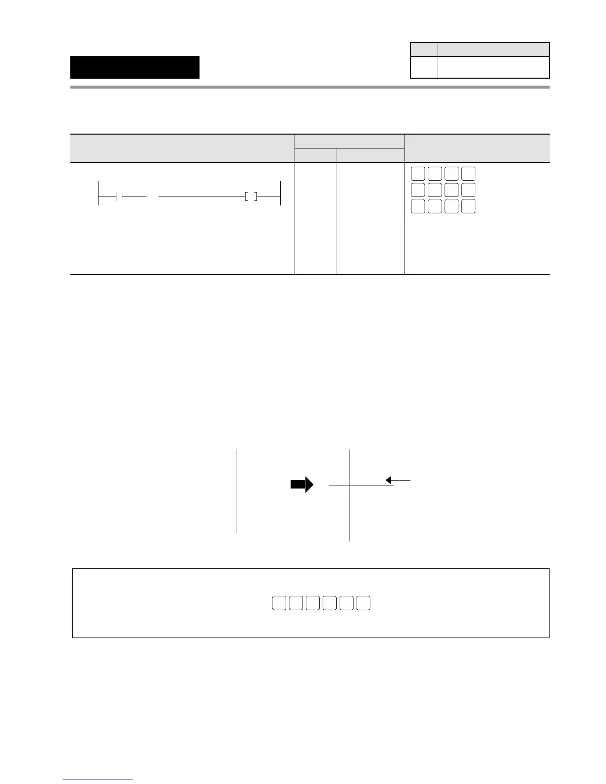
■ Explanation of example
• Y0 outputs when X1 turns ON.
Description
• The NOP instruction can be used to make the program easier to read when checking or
correcting.
• When the NOP instruction is inserted, the size of the program will increase slightly, however,
there will be no effect on the results of the arithmetic operations.
Example:
• To move the starting point of a program block from address 39 to address 40, insert a NOP
instruction to address 39.
This moves the starting point to address 40.
Notes:
• To delete the NOP instruction after editing in the PROG. mode, use the programming tools (NPST-GR:
DELETE ALL NOPS, FP Programmer II: OP1).
Operation procedure of FP Programmer II
• Refer to page 139, “5-4. Hints for Programming Basic Instructions”, for details about basic instructions,
such as the NOP instruction, which are not displayed on the FP Programmer II keys.