109
5-3. Description of Basic Instructions
DF/
Trailing edge differential
DF
Leading edge differential
Outline DF: Turns ON the contact for only one scan when the leading edge of the
trigger is detected.
DF/: Turns ON the contact for only one scan when the trailing edge of the
trigger is detected.
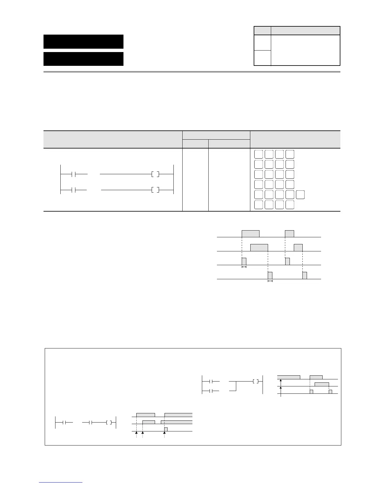
Program example
■ Explanation of example ■ Time chart
Description
• The DF instruction executes and turns ON output for only one scan duration when the trigger
changes from an OFF to an ON state.
• The DF/ instruction executes and turns ON output for only one scan duration when the trigger
changes from an ON to an OFF state.
• There is no limit on the number of times the DF instruction and DF/ instruction can be used.
Notes:
• The DF and DF/ instructions detect only the changes in the ON/OFF state of the contact comparing the
state in the scan before. Therefore, if its trigger is already set to ON at the first scan of the FP1’s operation,
there will be no execution of the DF instruction. And if its trigger is set to OFF, there will be no execution of
the DF/ instruction.
• With a circuit such as the one in the figure below, operation will be as follows.
1 When X1 is OFF, even if X0 rises, Y0 remains OFF.
2 Even if X1 rises when X0 is ON, Y0 remains OFF.
3 If X0 rises when X1 is ON, then Y0 will go ON for one scan.
• Y0 goes ON for only one scan when the leading edge
of X0 is detected.
• Y1 goes ON for only one scan when the trailing edge
of X1 is detected.
Ladder Diagram FP Programmer II key operations
Boolean Non-ladder
Address Instruction