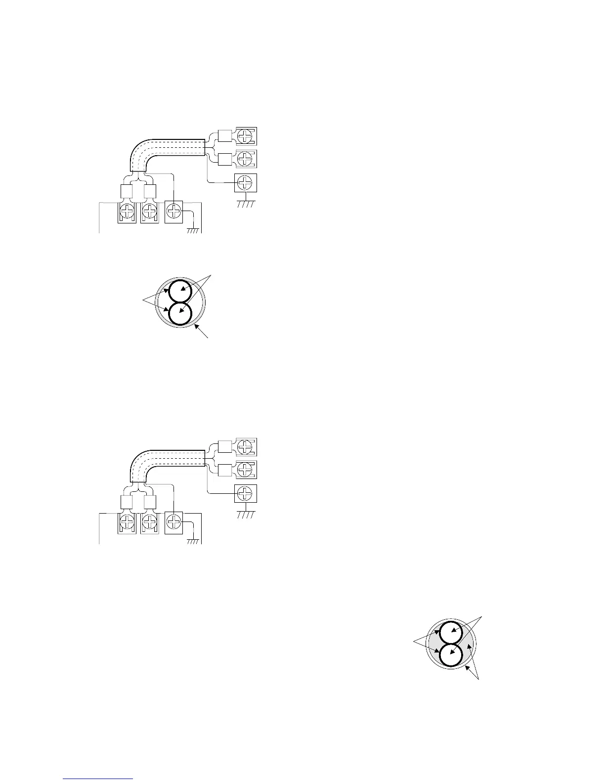
7. Wiring the FP1 Transmitter Master Unit
Connect the RS485 interfaces on the FP1 Transmitter Master Unit and on the other Programmable Controller with a
communication cable. When connecting the communication cable, be sure to connect positive (+) to positive, and
negative (-) to negative of the RS485 interface.
8. Wiring the FP1 I/O Link Unit
Connect the RS485 interfaces on the FP1 I/O Link Unit and on the other Programmable Controller with a
communication cable. When connecting the communication cable, be sure to connect positive (+) to positive, and
negative (-) to negative of RS485 the interface.
1) Cable Specifications
Vinyl Cabtyre Cable (VCTF): 2-conductor
• Conductor
Size: Min. 0.75 mm
2
(AWG18 or lager)
Resistance: Max. 25.1 Ω/km (at 20˚C/68˚F)
• Cable
Insulation thickness: Max. 0.6 mm/0.24 in.
Molding jacket diameter: Approx. 6.6 mm/2.60 in.
• Conductor
Size: Min. 1.25mm
2
(AWG16 or lager)
Resistance: Max. 16.8 Ω/km (at 20 ˚C/68 ˚F)
• Cable
Insulation material: Polyethylene
Insulation thickness: Max. 0.5 mm/0.020 in.
Jacket thickness: Approx. 8.5 mm/0.335 in.
 Loading...
