7 - 3
7 Digital I/O Slave Unit
GX-series EtherCAT Slave Unit User’s Manual
7-2 I/O Data Allocation (PDO Mapping)
7
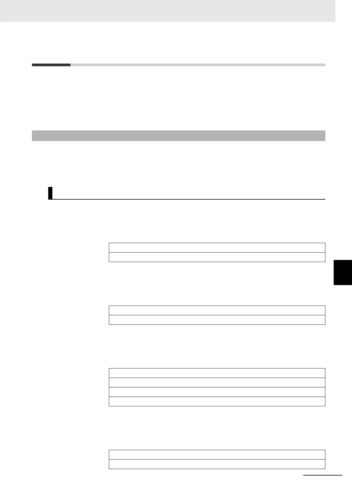
7-2-1 Input Data Allocation
7-2 I/O Data Allocation (PDO Mapping)
I/O data of Digital I/O Slave Units are allocated to the input/output areas of the I/O memory of the
EtherCAT Master Unit, respectively.
For the detailed explanation of allocation method, refer to the manual of EtherCAT Master Unit to be
connected.
The input data for a Digital I/O Slave Unit consists of the input data for the Slave Unit and the input data
for the Expansion Unit (when one is mounted). You can also assign the Sysmac error status.
*1
The
input data is assigned in this order in byte increments.
*1 Unit version 1.1 or later only.
8-point Input Slave Unit
16-point Input Slave Unit
32-point Input Slave Unit
8-point Expansion Unit
7-2-1 Input Data Allocation
Input data allocation example
Offset
(byte) 7 bit 0 bit
0 Input data of the Slave Unit (7 to 0 bit)
+1 Reserved
Offset
(byte) 7 bit 0 bit
0 Input data of the Slave Unit (7 to 0 bit)
+1 Input data of the Slave Unit (15 to 8 bit)
Offset
(byte) 7 bit 0 bit
0 Input data of the Slave Unit (7 to 0 bit)
+1 Input data of the Slave Unit (15 to 8 bit)
+2 Input data of the Slave Unit (23 to 16 bit)
+3 Input data of the Slave Unit (31 to 24 bit)
Offset
(byte) 7 bit 0 bit
0 Input data of the Expansion Unit (7 to 0 bit)
+1 Reserved

 Loading...