A Appendix
A - 76
GX-series EtherCAT Slave Unit User’s Manual
A-3 Precautions with Connecting
Two-wire DC Sensors
When using a two-wire DC sensor with a DC input type Slave Unit, check that the following conditions
have been met. Failure to meet these conditions may result in operating errors.
V
ON ≤ VCC - VR
VCC: I/O power supply voltage (The allowable power supply voltage range is 20.4 to 26.4 V, so 20.4 V will be
used here to allow for the worst possible conditions.)
V
ON: ON voltage for a Unit with DC inputs
V
R: Sensor's output residual voltage
It is sometimes possible to satisfy the above equation by adjusting the I/O power supply voltage (VCC)
to 26.4 V.
I
OUT (min) ≤ ION ≤ IOUT (max)
IOUT: Sensor control output (load current)
I
ON: ON current of a Unit with DC inputs
ION is calculated as follows:
I
ON = (VCC - VR - VF) / RIN
VF: Internal residual voltage of a Unit with DC inputs
R
IN: Input impedance of a Unit with DC inputs
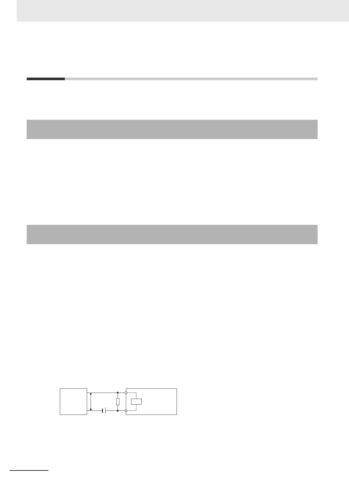
When ION is smaller than IOUT (min), connect a bleeder resistor R.
The bleeder resistor constant can be calculated using the following equation.
R ≤ (V
CC - VR) / (IOUT (min) - ION)
Power W ≥ (V
CC − VR)
2
/ R × 4 [allowable margin]
A-3-1 Relation between ON Voltage of a Unit with DC Inputs and Sensor
Residual Voltage
A-3-2 Relation between ON Current of a Unit with DC Inputs and Sensor
Control Output
2-wire
sensor
DC input
type slave
R
IN
V
R
R
V
CC

 Loading...