10 IO-Link Master Unit
10 - 18
GX-series EtherCAT Slave Unit User’s Manual
10-6 Communications Performance
This section describes the I/O response times of the GX-series IO-Link Master Unit.
The I/O response time is the time required for the following processing: The CPU Unit processes an
external signal input to one EtherCAT slave, and another EtherCAT (CoE) slave outputs the processed
result as an external signal.
This section describes the maximum I/O response time of the GX-series IO-Link Master Unit.
For the timing charts and calculation methods for EtherCAT slaves, refer to System Response Time in
Process Data Communications in the NJ/NX-series CPU Unit Built-in EtherCAT Port User’s Manual
(Cat. No. W505).
The following EtherCAT slave parameters are necessary to calculate I/O response times.
• Slave input response time: Specific input response time for EtherCAT slave
• Slave output response time: Specific output response time for EtherCAT slave
The parameter values and calculation methods for the GX-series IO-Link Master Unit are given below.
Input Data
*1 Pin_size: The larger of the total IO-Link input data sizes for IO-Link communications between ports 1 and 4 and
ports 5 and 8.
*2 For information on how to determine the IO-Link communications cycle, refer to "10-6-2 Determining the
IO-Link Communications Cycle" in Page 10 - 20Determining the IO-Link Communications Cycle.
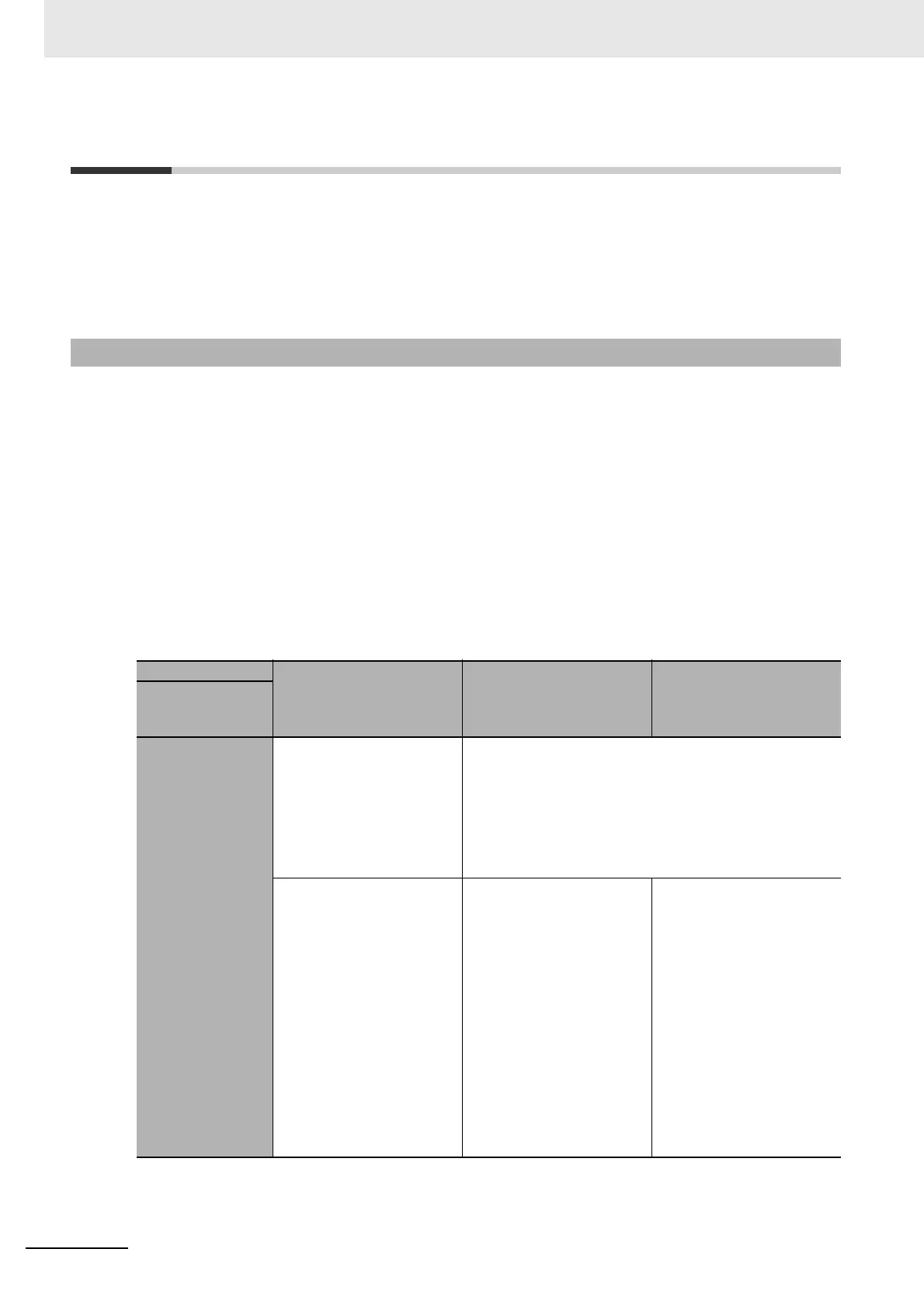
10-6-1 Maximum I/O Response Time
I/O data type IO-Link process input data
from IO-Link
communications in
IO-Link Mode
Digital input data for pin 2
in IO-Link Mode
Digital input data in SIO
(DI) Mode
Parameter
Slave input
response time
0.134
× Pin_size
*1
+ 0.012 × (Total size (in
bytes) of IO-Link process
input data from IO-Link
communications from port 1
to port 8) + 5.02+ IO-Link
communications cycle
*2
[ms]
0.134
× Pin_size
*1
+ 0.012 × (Total size (in bytes) of IO-Link process input
data from IO-Link communications from port 1 to port 8) +
5.02 + Input filter time [ms]
Example: When the IO-Link
input data sizes of the
IO-Link devices (sensors)
for port 1 through port 4 are
all 2 bytes, the IO-Link input
data sizes of the IO-Link
devices (sensors) for port 5
through port 8 are all 4
bytes, and the IO-Link
communications cycle for
those IO-Link devices
(sensors) is 2.1 [ms]: 0.134
× 4 bytes × 4 devices +
0.012
× Total of 24 bytes +
5.02 + 2.1 = 9.552 [ms]
Example: When the IO-Link
input data sizes of the
IO-Link devices (sensors)
for port 1 through port 4 are
all 2 bytes, the IO-Link input
data sizes of the IO-Link
devices (sensors) for port 5
through port 8 are all 4
bytes, and no input filter is
used: 0.134
× 4 bytes × 4
devices + 0.012
× To t a l o f
24 bytes + 5.02 = 7.452 [ms]
Example: When port 1
through port 7 are used by
IO-Link devices with an
IO-Link input data size of 2
bytes and port 8 is used by a
non-IO-Link device (sensor)
with no input filter: 0.134
×
2 bytes
× 4 devices + 0.012
× Total of 14 bytes + 5.02 =
6.26 [ms]

 Loading...