10 IO-Link Master Unit
10 - 4
GX-series EtherCAT Slave Unit User’s Manual
10-2 I/O Data Allocations: PDO Mapping
The data in the IO-Link Master Unit is allocated in the OUT and IN areas in the I/O memory of the
EtherCAT Master Unit.
Also, the Sysmac error status is allocated to the IN area of I/O memory of the EtherCAT Master Unit.
Refer to the manual of the EtherCAT Master Unit for allocation methods.
Precautions for Correct Use
Allocate the process input and process output data for IO-Link devices consecutively starting
from data 01. A setting error will occur if any data is skipped or not in order.
For unit version 1.1 or later, Digital Input Data and Digital Output Data are allocated by default.
Default values of I/O allocation differ between the IO-Link Master Unit with unit version 1.0 and
one with unit version 1.1.
If you replace the Unit with unit version 1.0 with one with unit version 1.1 or later, make the I/O
allocation same for both Units.
Replacing the Unit without changing the I/O allocation may result in erroneous output, erroneous
input, and a change in the timing of I/O.
The IO-Link Master Unit has the following types of input data. You can allocate the required data in the
IN area. You can also allocate Sysmac error status.
*1 Unit version 1.0 : No
Unit version 1.1 or later : Yes
*2 The digital input data collection function is supported in IO-Link Master Unit with unit version 1.1 or later.
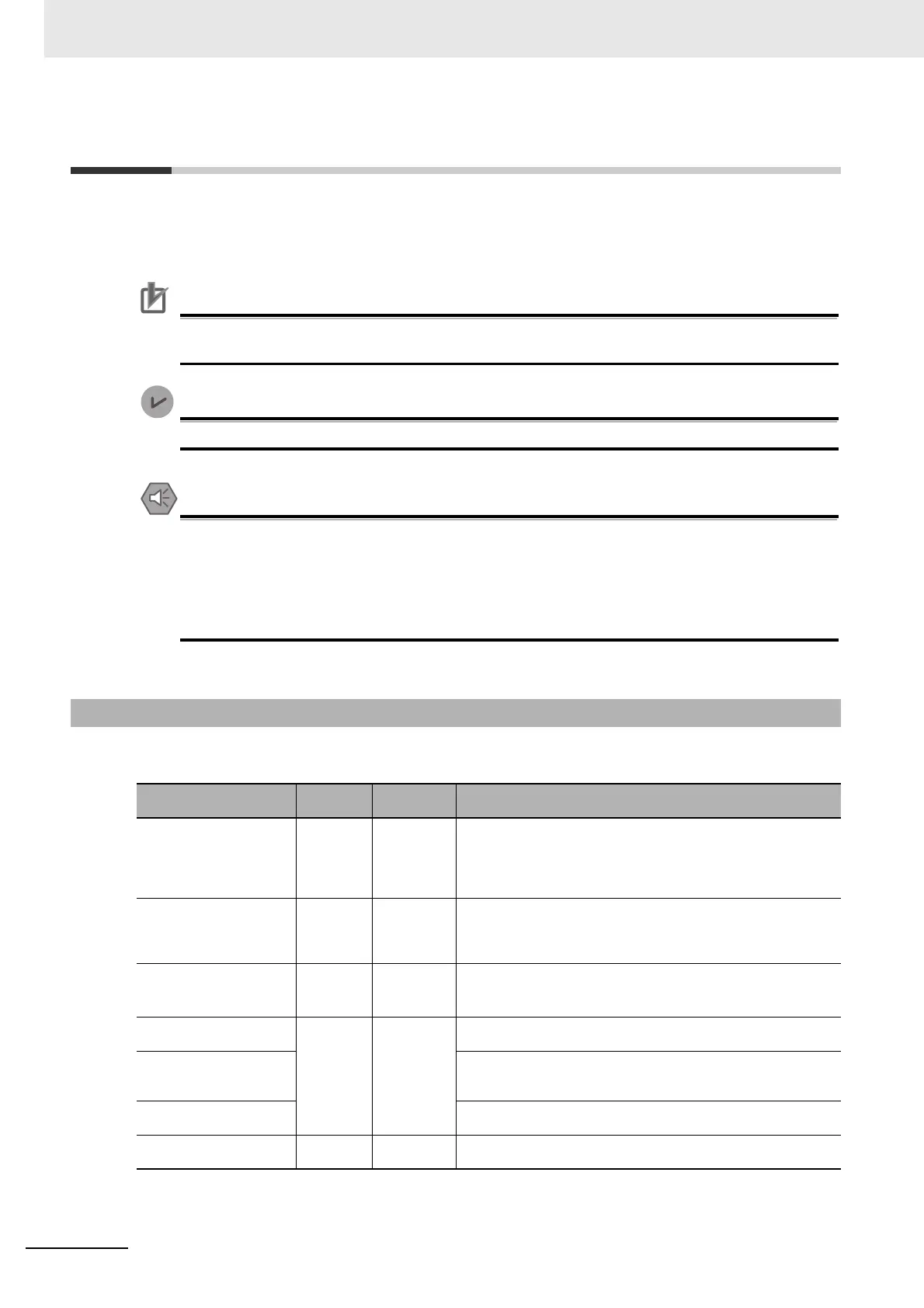
10-2-1 Allocating Input Data
Data name Size
Default I/O
allocation
Details
I/O Port Status 2 bytes Yes Indicates whether process input data (IO-Link input data, digital
inputs from Pin 2, and digital input data) is enabled or disabled for
each port.
Also indicates the status of the I/O power supply to the IO-Link
Master Unit.
I/O Port Error Status 8 bytes Yes Indicates the following errors for each port:
IO-Link communications error, short-circuit in I/O cable, device
configuration verification error, device I/O size error, PDO mapping
error, error-level device event, and information-level device event
Digital Input Data 2 bytes
*1
Digital inputs with Pin 2 in IO-Link Mode, data collected in IO-Link
Mode and when the digital input data collection function is enabled,
or digital input data in SIO (DI) Mode.*
2
Port 1 IO-Link Input Data 32 words ×
8 ports
Yes (2 bytes
per port)
This is the input data from IO-Link devices such as sensors that are
connected to port 1 in IO-Link Mode.
·
·
·
·
·
·
Port 8 IO-Link Input Data This is the input data from IO-Link devices such as sensors that are
connected to port 8 in IO-Link Mode.
Sysmac Error Status 1 byte Yes Contains status flags that are used to check errors that occur and
confirm when they have been eliminated.

 Loading...