4 - 11
4 Installation and Wiring
GX-series EtherCAT Slave Unit User’s Manual
4-3 Connecting to Unit Power Supply and I/O Power Supply
4
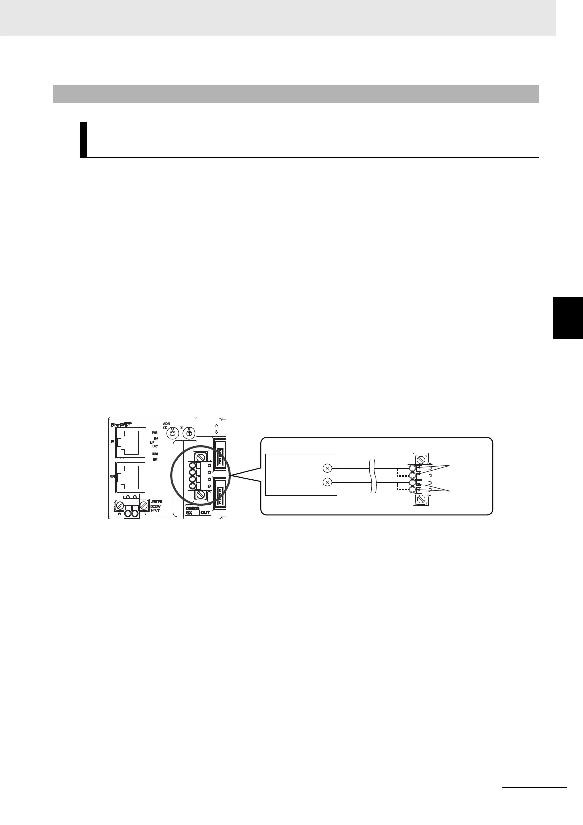
4-3-4 Connecting the I/O Power Supply
Units with screw terminal blocks
It supplies the 24-VDC I/O power to the I/O power supply terminal on each Slave Unit.
For the locations of I/O power supply terminals, see the terminal layout diagrams for each Slave Unit
or wiring diagrams in Chapter 7 to Chapter 10.
Moreover, for how to connect power supplies to terminals, refer to "4-4-1 Connecting to a Screw
Terminal Block" in Page 4 - 13.
Units with e-CON connectors
The following e-CON connector type Slave Units (Output Slave Units and output sections of
Input/Output Slave Units) are equipped with I/O power supply connectors to supply I/O power to
external devices.
• GX-OD1618/OD1628/MD1618 (output section only)/MD1628 (output section only)
• GX-OD3218/OD3228/MD3218 (output section only)/MD3228 (output section only)
To connect external devices to these Slave Units, supply the 24-VDC I/O power to the I/O power
supply connector.
Mount a pin terminal, or equivalent to the power supply cable so that it will not be displaced.
4-3-4 Connecting the I/O Power Supply
Digital I/O Slave Units, Analog I/O Slave Units, and Encoder Input
Slave Units
V terminal
G terminal
24-VDC
power supply
+
−

 Loading...