6 Basic Specifications of Slave Units
6 - 4
GX-series EtherCAT Slave Unit User’s Manual
6-3 Specifications of Common Areas
This section explains the specifications of indicator, switches, and connectors commonly mounted in
each Slave Unit.
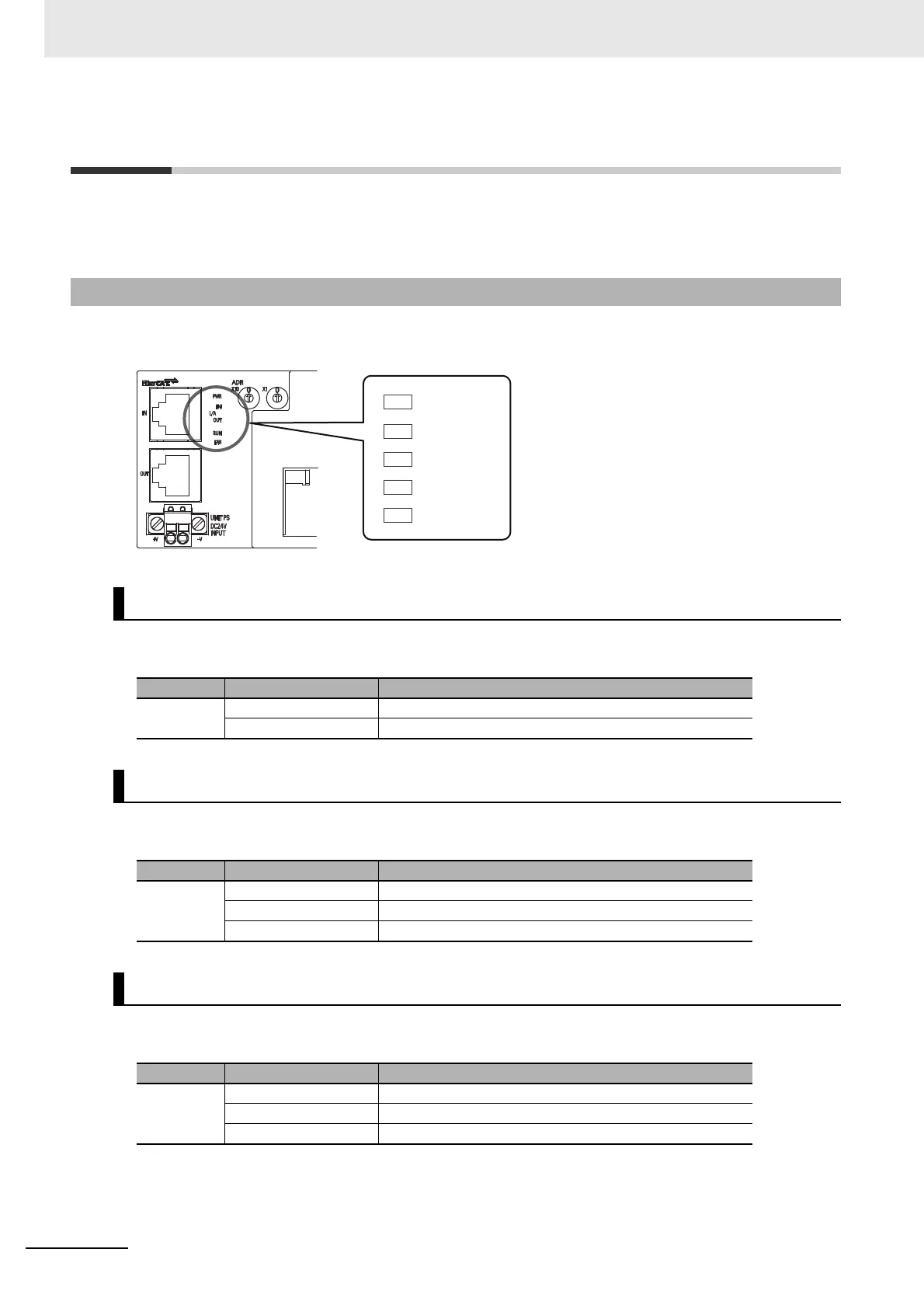
It indicates the current state of an EtherCAT Slave Unit.
Indicates the unit power supply state.
Indicates the communication state (input side).
Indicates the communication state (output side).
6-3-1 Status Indicators
[PWR] indicator
Color State Contents
Green
OFF Unit power OFF state
ON The unit power (24 VDC) is supplied to the Slave Unit.
[L/A IN] indicator
Color State Contents
Green
OFF Link not established in physical layer
Flickering In operation after establishing link
ON Link established in physical layer
[L/A OUT] indicator
Color State Contents
Green
OFF Link not established in physical layer
Flickering In operation after establishing link
ON Link established in physical layer

 Loading...